
Important Point
Axial Flow Turbine Example:
A gas turbine unit for power generation or a turbojet engine primarily consists of a compressor, combustion chamber, and a turbine for producing thrust. The air passing through the compressor experiences an increase in pressure.
The air is then pumped into the combustion chamber, causing a rise in temperature. This high pressure and temperature gas are then passed through a turbine, where it is expanded, & the required powers are obtained. Turbines, like compressors, can be classified into radials, axial, & mixed-flow machines.
In an axial machine, the fluid moves essentially in an axial direction through the rotor. In the radials type, the fluid motion is mostly radial. Mixed flow machines are characterized by a combination of axial & radial motions of the fluid relative to the rotor.
The choice of turbines type depends on the application, although it is not always clear which type is superior. Comparing axial & radial turbines of the same overall diameters, we can say that axial machines, such as in the case of compressors, are capable of handling significantly higher mass flows. On the other hand, for smaller mass flows, a radial machine can be made more efficient than an axial machine.
The radial turbines are capable of a higher pressure ratio per phase than the axial ones. However, multi-staging is much easier to arrange with axial turbines, so it is not difficult to achieve large overall pressure ratios with axial turbines. In this chapter, we will focus on axial flow turbines. Generally, the efficiency of well-designed turbines is higher than the efficiency of a compressor.
In addition, the design process is somewhat simpler. The main reason for this fact is that the fluid passes through the pressure drop in the turbine, and the pressure in the compressor is increased. The pressure drop in turbines is sufficient to make the boundary layer generally behave well, and the boundary layer separation that often occurs in compressors due to unfavorable pressure gradients in turbines can be avoided.
Offsetting this advantage is a much more significant stress problem because turbine rotors must operate in gas with very high temperatures. The actual blade shape is often more dependent on stress and cooling considerations than on aerodynamic considerations beyond the satisfaction of velocity-triangle requirements.
Due to the typically falling pressure in the turbine flow path, it is possible to bend a giving blade row further without danger of flow separation than an axial compressor blade row. This means a lot more work per stage and a significantly higher pressure ratio.
Advances have been made in recent years in turbine blade cooling and metallurgy of turbine blade materials. This means that the turbine is able to operate successfully at increasingly higher inlet gas temperatures, and substantial improvements are being made to the turbine engine thrust, weight, and fuel consumption.
Types of Axial Flow Turbines:
According to the works fluid, axial flow turbines can be steamed turbines, gas turbines, hydraulics turbines, horizontal axis wind turbines, or ocean currents turbines.
#1. Axial Flow Steam Turbine
Steam turbines work to convert the thermal energy available in steam into mechanical energy. They are used to generate electricity in thermal power plants. The steam is directed through a turbine to the multistage rotating blades driving the electric generator.
Such power plants use natural gas, fossil fuels, coal, or nuclear fuel. The steam turbine is a heat engine that achieves most of its advancement in thermodynamic efficiency by using several steps, which lead to a closed state for the ideal reversible expansion process.
Since the turbine creates rotational motion, it is particularly suitable for driving electric generators. For example, in 2014, the U.S. About 85% of all the electricity in the U.S. was generated using steam turbines. A turbo generator is a steam turbine connected to an electric generator.
Steam turbines were developed years before gas turbines. Therefore, the design of axial flow gas turbines is a result of the development of steam turbine technology.
#2. Axial Flow Gas Turbine
Axial flow turbines are the most widely used gas turbine using compressed fluid. Axial flow turbines supply mosts gas turbine units and are more efficient than radial turbines in most working ranges. Gas turbines are the combustion engines at the heart of a power plant converting natural gas or other fuel into mechanical energy.
Then, the energy drives a generator that generates electricals energy. The high-temperatures pressurized gas from the combustion engine enters the gas turbine and produces a shaft work output. This action also causes the compressor to run; In a turbojet engine, the remaining energy has to be redeployed for external work, including directly generating thrust, rotating a fan, propeller, or other independent turbine connected to an electric generator.
#3. Types in Terms of Energy Conversion Method
Accordingly, axial flow turbines can be divides into two generals categories: impulse turbines and reaction turbines. In impulse turbines, the entire enthalpy drop occurs between the nozzles; Therefore, the flow velocities entering the rotor are very high. On the other hand, the structure of reaction turbines is such that there is an enthalpy drop between the nozzle and the rotor.
3.1. Impulse Turbine
The impulse turbine has the simplest basics of all turbines. In a gas turbine, this includes a set of nozzles followed by a row of blades. As the gas expands into the nozzle, its high thermal energy is converted into kinetic energy. It can be represented by the follows equation:
V_{inlet}=\sqrt{2\Delta h_{0}}Vinlet=2Δh0
The high-velocity gas hits the blades, and most of the kinetic energy of the moving gas flow is diverted to the work of the turbine shaft.
The following figure displays a schematic diagram of a single-stage impulse gas turbine. In the nozzle, the static pressure decreases as the absolute velocity increases. Then, the absolute velocity in the rotor decreases; However, the static pressure and relative velocity do not change.
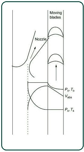
For maximum energy transfer, the blade has to rotate at about half the velocity of the gas jet. Two or more moving blade rows are sometimes implemented with a single nozzle to reduce blade tip speed and wheel tension. Between the moving blade rows are guide vanes that redirect gas from one moving blade row to another—Curtis turbines—(next figure).
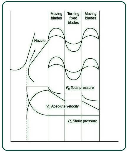
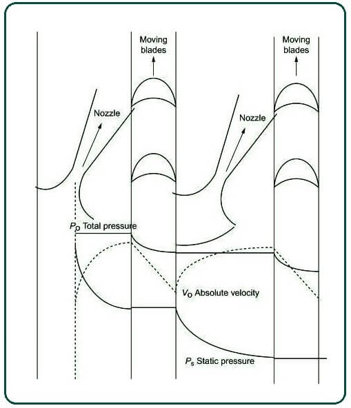
Another impulse turbine is the Rate Turbine, in which the work is done in different stages. Each stage includes a nozzle and a row of blades. So, a portion of the entire kinetic energy of the jet flow is absorbed by each stage of the turbine as useful work. The air from the first row of moving blades enters the next set of nozzles to further reduce the enthalpy. The velocity increases, and another part of the kinetic energy are absorbed into the associated row of moving blades.
In the following figure, the flow velocity and pressure distribution through a Rate turbine are shown. It should be noted that except for some friction loss, the total pressure and temperature in the nozzle remain constant.
In an impulse turbine, the entire enthalpy drop is taken at the nozzle, and the outlet velocity from the nozzle is greater. Thus, by definition, the degree of response of an impulse turbine is equal to zero. Since there is no change in enthalpy in the rotor, the relative velocities entering the rotor and exiting the rotor blades are the same. Absolute exhaust velocity must be axial to achieve the maximum utilization factor. Thus, the wind angle (α) can be calculated by:
\cos \alpha=\frac{2U}{V_{inlet}}cosα=Vinlet2U
The subscript ‘inlet’ represents the turbine rotor inlet, and u is the blade speed. Typically, α is small, ranging from 12° to 25°.
The optimum value of the U/Vinlet is a measurement that indicates the maximum energy transfer to the shaft. It also represents a deviation from the desired design value of cos α, leading to a loss of energy transfer. In off-design conditions, the loss is increased due to the incorrect gas attack angle with respect to the rotor blades. The maximum step efficiency is at or near the value of α expressed above.
The power generated by the flow along an impulse turbine is determined using the Euler equation:
P=\dot{m}U(V_{\theta,inlet}-V_{\theta,outlet})P=m˙U(Vθ,inlet−Vθ,outlet)
In the above equation, Vθ is the tangential component of the absolutes velocity.
For the maximums utility factors, this equation can be rewritten as:
P=\dot{m}U(V_{\theta,inlet}\cos \alpha)P=m˙U(Vθ,inletcosα)
In pure impulses turbines, the relative velocity remains unchanged, except for the effects of friction & turbulence. Losses can range from about 20% for high-velocity turbines to about 8% for low-velocity turbines.
3.2. Reaction Turbine
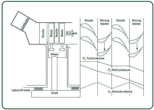
Axial flow feedback turbines are the most widely used turbines. In a reaction turbine, both the nozzle and the blades serve as extensions of the nozzle. So, the static pressure decreases in the still and moving blades. The stationary blades act as nozzles and guide the flow towards the moving blades at a velocity somewhat higher than the speed of the moving blades.
In a reaction turbine, the velocities are normally very low, and the relative velocities entering the blades are approximately axial. The following figure shows a schematic view of a reaction turbine.
A 100% reaction turbine with a degree of response equal to 1 is not practical due to the high rotor speed required for a good utilization factor.
The 50% reaction turbine is widely used and has a special strength. The velocity diagram for such a reaction turbine is symmetric, and the outlet velocity must be axial to reach the maximum utilization factor. The angles of the fixed and rotating blades are equal. So, for maximum use, we have:
\cos \alpha=\frac{U}{V_{inlet}}cosα=VinletU
The power produced by the reaction turbines are calculated using the general Euler equation:
P=\dot{m}U(V_{\theta,inlet}\cos \alpha)P=m˙U(Vθ,inletcosα
The work produced by impulse turbines with a single-stage operating at the same rotation speeds is twice that of a reaction turbine. Therefore, the cost of reactions turbines is much higher for the same amount of work because it requires more stages.
Additionally, the reaction turbine has a higher efficiency due to the blade suction effect. Thus, it is very common that impulses stages are used in the first few stages of a multistage turbine, followed by 50% response turbines to maximize pressure reduction.
This combination leads to an effective compromise because an all-impulse turbine has very low efficiency & all-reaction turbines have an excessive number of stages.
Axial Flow Hydraulic Turbines:
The working fluid in hydraulic turbines is water. A very common example of axial hydraulics turbines is the Kaplan turbine. A hydraulic turbine is a turbomachine that converts available potential energy in an elevated waters body such as rivers or reservoirs into rotational mechanical energy. The Kaplan is a propeller-type water turbine that applies the principle of reaction turbines to extract energy from a fluid by changes in the pressure of the water passing through the turbine.
Also, Read: What Is Reaction Turbine? | Reaction Turbine | Working of Reaction Turbine | Parts of Reaction Turbine
Axial Flow Wind Turbine:
Horizontal axis wind turbines have their own axes of rotation that are horizontal to the ground and almost parallel to the wind stream. Most commercial wind turbines are from these turbines. Horizontal axis wind turbines have their own axes of rotation that are horizontal to the ground and almost parallel to the wind stream.
Most commercial wind turbines are from these turbines. A wind turbine converts wind kinetic energy into mechanical energy. It can also be applied directly for mechanical purposes such as pumping water or grinding grain and generating electricity.
Axial Flow Marine Turbines:
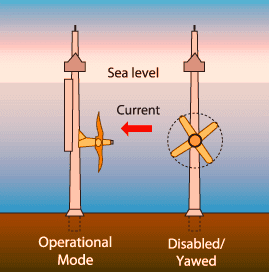
Axial flow sea turbines are similar to the typical horizontal axis wind turbines described above. The rotors of these turbines, equipped with blades at one end, are mounted on a vertical beam that is fixed to the seafloor. When the current flow rotates the blades, the turbine spins and generates electrical energy.
The energy used by an axial flow turbine can be maximized because the flowing area of the blades includes the current flow direction. Therefore, in some forms of axial flow turbines, the rotor may yawn depending on the direction of the current flow.
P=0.5C_{p}\rho A V^{3}P=0.5CpρAV3
Where is the fluid density, A is the swept area of the axial flow turbine, V is the fluid velocity, Cp is the power coefficient which normally varies between 0.35–0.5 for marine turbines.
Performance Analysis Procedure of Axial Flow Turbine:
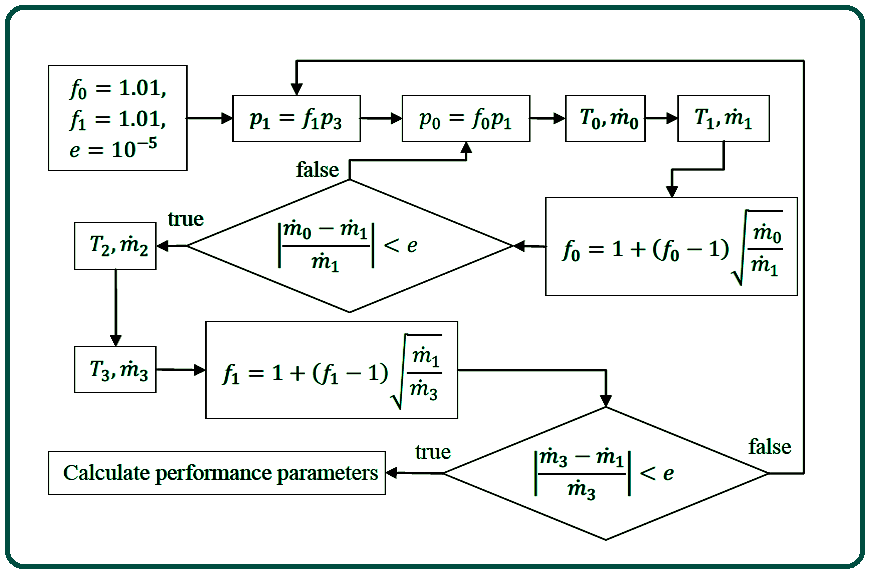
The purpose of the performance analysis process is to calculate critical turbine performance parameters for a turbine rotating at a specified speed over a range of pressure ratios. The pressure ratio varies by keeping the turbine stage inlet total temperature and total pressure constant and by changing the outlet constant pressure, as is optimal for turbine analysis (Mitchell, 1982).
For each value of the constant exhaust pressure, the mass flow through the stage and the average radius gas across the stage are calculated. These states are used in the calculation of turbine performance parameters. Process flow chart to calculate turbine performance parameters for each outlet static pressure value.
With the specified outlet constant pressure, estimates are made for the intermediate static pressure in the turbine stage. These estimates are revised until the mass flow through the engine becomes constant in all sections. Once the mass flow through the four turbine sections converges to a single value, the turbine performance parameters are calculated.
#1. Stator Inlet State
Combustion gases enter the turbine stage with purely axial velocity and Known total temperature and total pressure. Static pressure based for one phase outlet State solution, the static inlet pressure is estimated. Therefore, for For the purposes of state calculation at the stator inlet, the static inlet pressure is also Considered as a known quantity.
To obtain the mass flow rate at the stator inlet is The static properties are first determined by applying isentropic relations. Ns The difference between the total and constant enthalpy is then used to obtain the flux Velocity at the mean radius. This velocity is then multiplied by the mean radius Static density and inlet flow area to obtain mass flow at the stator inlet.
#2. Stator Exit State
In solving the stator exhaust condition, it is assumed that the flow is in line with the blade angle as it leaves the trailing edge. Additionally, since stator blade no. Provide works to flow, and there is no heat loss; the total enthalpy is conserved at Blade Row.
Hence the total temperature and enthalpy at the stator are known Go out. The total pressure in the row of stator blades does not remain constant due to the Loss of pressure in the row of blades.
The relative total pressure loss coefficient, 𝑌, is used to quantify these losses and is defined as the ratio of the relative total pressure loss across a blade row to the exhaust relative dynamic pressure of the blade row:
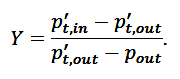
𝑌 is dependent on the blade geometry, the flow velocities, and gas properties on either side of the blade row. Therefore, since the flow field and gas properties are also dependent on 𝑌, an iterative procedure is required to solve the exit state.
An initial guess of 𝑌 is made, facilitating the calculation of the exit state. The resulting gas properties and flow field are then used to calculate a new total pressure loss coefficient, and the process is repeated until the loss coefficient has converged.
For the stator blade, the relative total pressure loss coefficient becomes the absolute total pressure loss coefficient since the blade row is stationary. The definition of 𝑌𝑆 is rearranged with the exhaust total pressure as the independent variable.

The isentropic relation for an ideal gas with varying specific heat is used to relate the total-to-static specific temperature-dependent entropy difference to the total to-static pressure ratio at any given state.
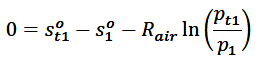
The following expression for the static specific temperature-dependent entropy at the stator blade exit:

Since the resulting value is only dependent on temperature, the static temperature and the other static properties at state one can also be found.
The static density and flow velocity magnitude is obtained as is done for the stator inlet state. However, unlike at the stator inlet state, the flow is not purely axial since it conforms to the exit blade angle.
Therefore, the axial projection of the stator exit velocity is multiplied by the corresponding gas density and flow area to yield the mass flow rate at this position.
#3. Rotor Inlet State
The blade height and mean radius may change between the stator exit state and the rotor inlet state. The change in mean radius has an effect on the circumferential velocity.
This effect is modeled by enforcing the conservation of angular momentum. The angular momentum of a fluid particle at the mean radius of state 1 is

The conservations of angular momentums dictate that a fluid particle at the mean radius of state two should have the same angular momentum as state 1. Assuming equal masses for the particles at the two states, the relationship between the two circumferential velocities can be shown to be

Changes in the annular dimensions also change the annular cross-sectional area. This change in the field is treated as either an isentropic nozzle or an isentropic diffuser, depending on the indication. In such isotropic nozzles and diffusers, the total temperature and pressure remain constant. Hence the total properties at the rotor inlet are known.
The static properties at the rotor inlet are calculated using an initial estimate of the static gas density and assuming that the mass flow rate remains constant from state 1 to state 2. This estimated value is used to calculate the constant temperature and pressure in state 2, from which a new density is calculated.
These processes are repeated until the values of the static density at the rotor inlet change, indicating that the true static properties have been calculated. In-state 2, the relative flow velocity and relative total gas properties become relevant. The relative circumferential velocity at state two is given by:
![]()
Since the motion of the blades are perpendiculars to the axial direction, there is no difference between the absolute and relative axial-flow velocity. The relative flow velocity at state two is therefore given by

This relative velocity is used to calculate the relative total gas enthalpy and pressure at state 2. State 2 is a sample count of the last iteration in the calculation.
#4. Rotor Exit State
The process of resolving the rotor exhaust position is similar to the process of resolving the stator exhaust position. The main differences between the two cases are that since the rotor does work by flux, the total enthalpy changes between state two and state 3.
However, it can be shown that the relative total enthalpy for the constant radius axial-flow blade row remains constant across the blade row (Dixon, 1998). The same approach is therefore used to determine the stator exhaust flow properties, with all aggregate properties being replaced by relative aggregate properties.
The mass flow rate is calculated using the axial projection of the relative rotor exhaust velocity. The absolute velocity and total flow properties are then calculated from the constant and relative properties and velocity.
#5. Calculating Turbine Stage Performance Parameters
The performance parameters of a turbine stage operating at a specified total-to-static pressure ratio are the total-to-total pressure ratio, the mass flow rate, and the total-to-total efficiency.
The mass flow rate is calculated in the last state calculation iteration, and the total-to-total pressure ratio can also be obtained directly from these calculated values. The total-to-total efficiency, however, is calculated from the equation:

The ideal rotor exhaust total enthalpy is calculated using isentropic relations and assuming that the total-to-total pressure ratio remains unchanged.
Also, Read: How to Fix a Leaking Car Roof | Why Water Leaks into Car from its Roof? | Why Is Water Leaking into My Car?
Frequently Asked Questions (FAQ)
Axial Flow Turbine Example
Axial flow turbine: The flow of water is in the direction parallel to the axis of the shaft. Example: Kaplan turbine and propeller turbine.
Types of Axial Flow Turbines
- Axial Flow Steam Turbine
- Axial Flow Gas Turbine
- Types in Terms of Energy Conversion Method
Axial Flow Turbines
Axial flow turbines, or horizontal axis turbines, closely resemble typical horizontal axis wind turbines. The rotors of axial flow turbines, with blades at one end, are installed on a vertical beam fixed on the seabed. As the current flow turns the blades, the turbine starts to spin and generate electrical energy.
Like this post? Share it with your friends!
Suggested Read –
- Water Jet Machining Diagram
- Difference Between Orthogonal and Oblique Cutting | Orthogonal Machining
- What Is Magneto Ignition System | How Does an Ignition System Work | How Does a Magneto Work | What Does a Magneto Do | Magneto Ignition System
- What Is a Synchromesh Gearbox? | Principle of Synchromesh Gearbox | Construction of Synchromesh Gearbox | Working of Synchromesh Gearbox
- Working of Constant Mesh Gearbox | What Is a Constant Mesh Gearbox? | Different Gear Ratios in Constant Mesh Gearbox | Construction of Constant Mesh Gearbox
- What Is Cupola Furnace? | Cupola Furnace Design । Cupola Construction | Purpose of Cupola | Working Principle of Cupola Furnace: | Advantages of Cupola Furnace | Disadvantages of Cupola Furnace | Applications of Cupola Furnace