Important Point
Tesla Turbine Generator:
#1. Definition
The Tesla turbine generator was invented in 1913 by none other than Nikola Tesla. It employs the occurrence of the boundary layer rather than the effect of the fluid on the surface of the blade. This is a low-torque high-rpm motor.
Thus, applications may be somewhat restricted in the commons sense of what we think of uses for other devices. However, Tesla himself envisions employing them in vehicles & others highly practicals matters.
#2. History
Dr. Nikola Tesla is most famous for his work with alternating current (AC) type power, but did you know in 1913, he also invented a bladeless form of turbomachinery? The Tesla Turbine was created when he was attempting to build a lighter engine to fulfill his ultimate objective of building a “flying machine.” Multi-disc, friction, shear-force, and boundary layer turbomachinery are all terms employed to describe Tesla-type turbines.
Tesla wrote in a 1912 article showing a small device that produced 110 hp and was “the size of a Derby hat.” The article featured a picture below to show how small it was. It had a single-stage, ran at 9,000 rpm, used 38 lbs of saturated steam per hp hour, & had a steam pressure of 125 lbs at the inlet. By compounding, Tesla claimed it could reduce it to eight pounds per hp hour.
Their new design employed two common fluid properties, viscosity, and adhesion, with several flat steel discs arranged closely on the shaft, reducing turbine efficiency. The rotor and disc are enclosed in housing when used as a turbine, and fluid is injected through a nozzle on the side of the disc. Due to viscosity and adhesion, the injection fluid moves inward onto the disc, forcing it to rotate. In the following, the fluid flows out of the segments around the shaft.
If used as a pump or compressor, the fluid is pumped through holes near the shaft and in an upward spiral on the disc. It finally exits the rotors through diffusers, like volute scrolls.
Tesla emphasized the simplicity, cost-effectiveness, & serviceability of its innovative design. It’s also possible to steer it in any direction, which is really cool.
Tesla also demonstrated a smaller pump powered by a 1.5 hp electric motor, which pumps 40 gallons of water per minute a 9-foots head during that interview in 1912.
So what? Still, all the concepts engineers designs are bladed pumps and turbines for users. The main problems are that Tesla’s goal of 95 percent efficiency has never been achieved. Despite nearly a century of effort, this style of design has only a few applications.
The lack of actual data is part of the problem. As a result, determining the precise efficiency of a Tesla turbine is a moving goal. Professor Warren Rice provided an article about Tesla’s turbomachinery at the 1991 International Tesla Symposium. His paper studies the research and commercial use of Tesla turbines up to that moment. But many are not.
Despite the apparent simplicity, the Tesla turbine design has some serious engineering problems. While it is powered, the efficiencies are no better than with bladed designs, and in some situations, much worse. The efficiency of the rotor is very good, but it requires the waste caused by the nozzle and diffuser to reduce it dramatically. Watch this video to see its performance.
Highly viscous or abrasive working fluids seem to be the best feature. According to Tesla, they can be used to capture the geothermal energy.
Professor Rice’s research gives many interesting insights, such as how this type of design avoids caveats and is very cool. “That got me thinks about submarines or aerospace uses, but I couldn’t find any references about the use of this type of turbine in those situations,” says Rice. Rice also mentions that new materials such as ceramics could make the design more feasible in the future.
Also, Read: Transformer | Construction of Transformer | Types of Transformers based on Cooling Method
How Tesla Turbine Generator Works:
Nikola Tesla, the prodigy and genius who arrived in New York City in 1884, is known to most as the father of the alternating current, the form of electricity that supplies electricity to nearly all homes & businesses. But Tesla was the prodigious inventor who applied his talents to a wide range of practical problems.
All told, it holds 272 patents in 25 countries, with 112 patents in the United States alone. You might imagine that, throughout all this work, Tesla would have kept his inventions in electrical engineering—which describe a complete system of generators, transformers, transmission lines, motors, and lighting—most dear to his hearts. But in 1913, Tesla received patents for what he described as his important mosts invention.
That invention was turbines known today as the Tesla turbine, boundary layer turbine, or flat-disc turbine generator. Interestingly, using the word “turbine” to describes Tesla’s inventions seems a bit misleading. This is because most people think of a turbine as a shaft with blades – like fan blades – attached to it. In fact, the Webster dictionary defines a turbine as an engine that is driven by the force of gas or water on the fan blades.
But Tesla turbines have no blades. It consists of a series of closely packed parallel discs attached to a shaft & arranged within a sealed chamber. When fluids are allowed to enter the chamber & pass between the discs, the disc turns, which in turn rotates the shafts; this rotary motion can be used in many ways, from power pumps, blowers, and compressors to running cars & airplanes.
In fact, Tesla claims that the turbine was the most efficient & most simply designed rotary engine ever produced. If these true, why hasn’t the Tesla turbine generator become more widely used?
Why hasn’t it becomes as ubiquitous as Tesla’s other masterpieces, AC Power Transmission? These are important questions, but they are secondary to more fundamentals questions, such as how does the Tesla turbine work & what makes the technology so innovative?
We will answer all this is a question in the next few pages. But first, we need to review some basics about the different types of engines that have been developed over the years. On the next page, we’ll get a better idea of the specific problem Tesla was hoping to solve with its new invention.
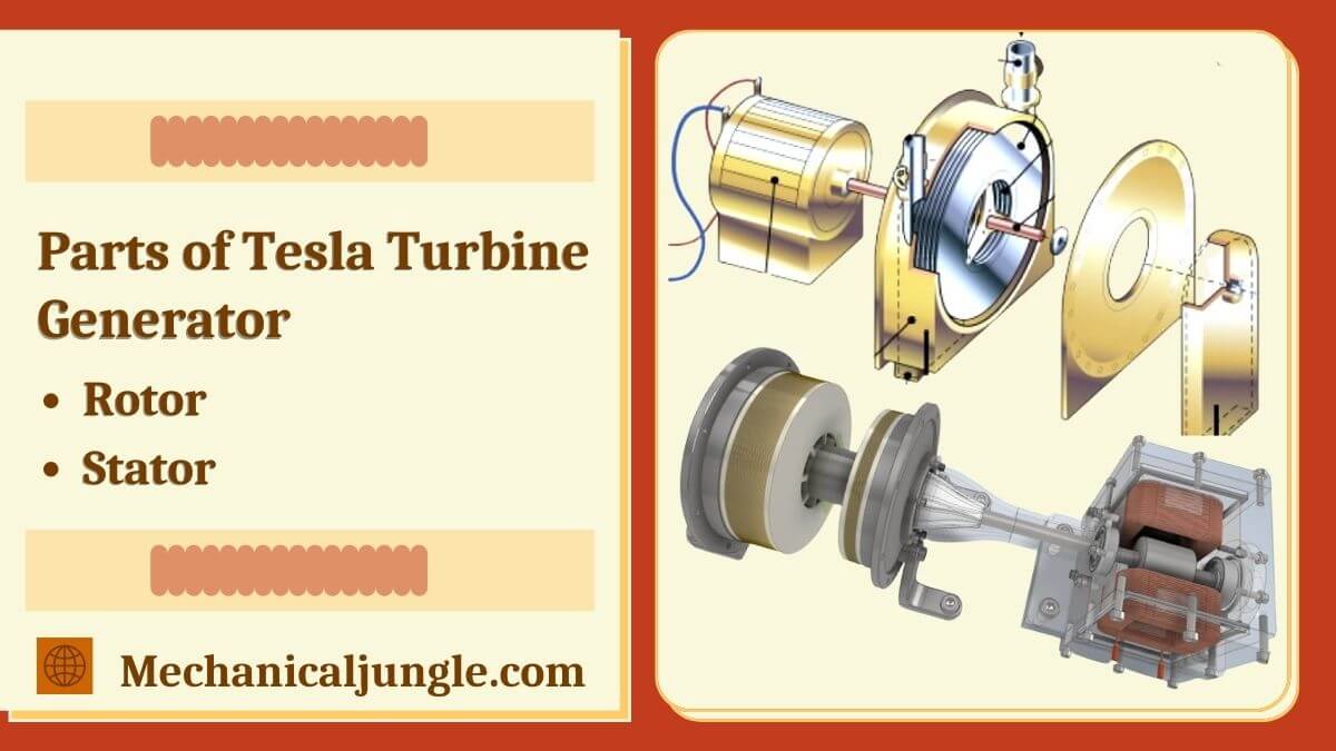
Parts of Tesla Turbine Generator:

Compared to pistons or steam engines, the Tesla turbine generator itself is simple. In fact, Tesla described it these ways in an interview appearing in the New York Herald Tribune on October 15, 1911: “All it requires is a few discs mounted on a shaft, separated and covered a short distance so that the fluid If possible, enter at one point and exit at another.” Clearly, these are oversimplifications, but not by much. Let’s look at two basic parts of turbines – the rotor and the stator – in more detail.
#1. Rotor
In a conventional turbine, the rotor is a shaft with blades attached to it. Tesla does away with the turbine blades and instead uses a series of discs. The size and number of disks may vary depending on factors related to a particular application.
Tesla’s patent paperwork does not define a specific number but uses a more general description, saying the rotor must have a “multiplicity” of discs with “appropriate diameters.” As we will see later, Tesla himself experimented a lot with the size and number of discs.
Each disc is made with an opening surrounding the shafts. These openings act as exhausts ports through which fluids exit. Metal washers are used as dividers to ensure that fluid can pass freely between the discs. Again, the thickness of the washer is not strictly set, although the space between usually does not exceed 2 to 3 millimeters.
A threaded nut holds the disc in position on the shaft, the last piece of the rotor assembly. As the discs are attached to the shaft, their rotation is transferred to the shaft.
#2. Stator
The rotor assembly is located within the stationary part of a cylindrical stator or turbine. To accommodate the rotor, the diameters of the inner chamber of the cylinder must be slightly larger than that of the rotor disc itself. Each end of the stator has a bearing for the shaft.
The stator also has one or two inlets into which nozzles are inserted. Tesla’s original design required two inlets, allowing the turbine to be run clockwise or counterclockwise.
This is the original design. To drive the turbine, a high-pressure fluid enters the nozzles at the stators inlets. The fluid passes between the rotor discs & causes the rotors to spin. Finally, the fluid exits through the exhaust ports at the center of the turbine.
One of the greats things about the Tesla Turbine is its simplicity. It can be made with lightly available materials, and the distance between the discs does not need to be precise controls. It’s so easy to build facts, and many mainstream magazines have included assemblies instructions using household materials.
Septembers 1955 issues of Popular Science featured a steps-by-steps plan for building a blower using a Tesla Turbine design made out of cardboard! But how exactly does a series of discs produce the rotary motion we expect from a turbine? This is the question we will cover in the next section.
Tesla Turbine Design:
Two inlet pipes are uses in the design, one of which is connected to the air hose pipe. One can use one of the two inlets as input. The rotor discs are mounted inside the body and are connected by bolts. All discs are connected to the outer body by a common shaft.
If it is being used as a pump, for example, the shaft is connected to the motor. There is a thin air gap between the discs, through which air flows and causes the disc to spin. The air gap can cause air molecules to be pulled over the disc.
Input air can be sent into the atmosphere through 4-5 holes in the front & rear covers. The holes are positioned in such’s a way that they generate vortexes, which causes the air to expand at a high rate. This high-speed air creates a high-speed pull on the disc, causing it to spins at extremely high rates. The disc gaps are one of the most important designs & efficiency characteristics for a turbine. The ideal gap size to maintain the gap layer is determined by the peripheral velocity of the disc.
Also, Read: What Is Reaction Turbine? | Reaction Turbine | Working of Reaction Turbine | Parts of Reaction Turbine
Tesla Turbine Design Calculations:
A number of design aspects are necessary to achieve high efficiency. Some of the main design calculations are as follows: The working fluid or inlet air pressure must be kept at a minimum level. If it is water, then the pressure must be at least 1000 kg/m.
A peripheral acceleration of 10e-6 m2/s is required. The angular velocity and circumferential velocity of the disc are used to calculate the difference between them. It is determined by the Polhausen parameter, which is based on constant velocities.
The flow rate of each disc is obtained by multiplying its cross-sectional area by its velocity. The number of disks is estimated based on the data. The diameter of the disc is, once again, critical to good efficiency.
Tesla Turbine Efficiency:
The ratio of output shaft power and input shaft power determines efficiency. It is written like this:
{\eta }_{Turbine}=\frac{{W}_{Shafts}}{{W}_{Water Horsepower}}=\frac{\omega {T}_{Shafts}}{\rho gHv}ηTurbine=WWaterHorsepowerWShaft=ρgHvωTShafts
Efficiency is determined by various elements, including shafts diameter, blade speed, blade number, load attached to the shafts, and so on. Compared with other conventional turbines, turbine efficiency is often high. Efficiency could potentially reach 97 percent for smaller applications.
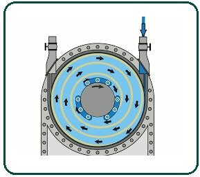
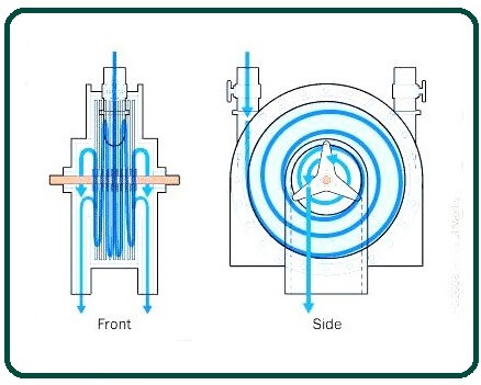
Working Principle:
Tesla Turbine generator is based on the boundary layer idea. It is composed of two inlets. In most cases, water or air are employed as the inlets of the turbine. The turbine’s body is made up of rotor discs which are attached by bolts. The discs are all connected by a common shaft.
The front casing and rear casing are the two cases that make up the body of the turbine. There are 4 to 4 holes in eaches case. All of these elements, such as the number of discs & disc diameter, play a part in determining the efficiency of the turbine.
Air enters the body of the turbine when it is allowed to flow through the pipe. Discs connected to each other are arranged inside the body of the turbine. The discs are separated by smalls air gaps. The discs are pulled in by air molecules as they enter the turbine body.
The discs tend to spin as a result of the drag. The front and rear covers have holes so that air can enter and exit through them. The holes are set in such ways that a vortex of air or water is created within the disc body. As a result, the discs are subject to additional drag from the air.
As a result, the disc spins at a very high speed. At low speeds, the amounts of contact between the vortex and the disc are small. However, when the wind accelerates, this contact increases, causing the disc to spin at a much faster rate.
The centrifugal force of the disc tries to push the air outwards. Yet, apart from openings in the front and rear covers, the air has nowhere to go. As a result, the air moves out, and the vortex is stronger. The rotational speed of the disc is almost the same as the rotational speed of the airflow.
Also, Read: Types of Impulse Turbine | Working Principle of Impulse Turbine | Components of on Impulse Turbine
Tesla Turbine Operation:
You might wonder how the energy of the fluid can make the metal disc spin. After all, if the disc is perfectly smooth and there are no blades, vanes, or buckets to “hold” the fluid, then logic suggests that the fluid will simply flow over the disc, leaving the disc motionless.
This, of course, does not happen. The rotor of the Tesla Turbine not only spins – it spins rapidly.
The reason can be found in two fundamental properties of all liquids: adhesion and viscosity. Adhesions are the tendency of dissimilar molecules to stick together due to attractive forces. Viscosity is the resistance of a substances’ flows.
These two properties work together to transfer energy from the fluid to the rotor or vice versa in a Tesla turbine. This way:
- As the fluid moves through each disc, the adhesive force slows down and sticks the fluid molecules just above the metal surface.
- Molecules immediately above the molecules on the surface slow down when they collide with the molecules attached to the surface.
- These molecules, in turn, slow down their upward flow.
- The farther one goes from the surface, the lesser is the collision with the surface of the object.
- At the same time, the viscous forces cause the molecules of the liquid to oppose separation.
- This produces a pulling force that is transmitted to the disc, causing the disc to moves in the directions of the fluid.
The thin layer of fluids that interacts with the surface of the disc in this way is called the boundary layer, & the interaction of the fluid with the solid surface is called the boundary layer effect.
As a result of these effects, propels fluid follows an increasingly accelerated spiral path along the face of the disc until a suitable exit is reached.
As the fluid moves in natural paths of least resistance, free of obstacles and disruptive forces caused by vanes or blades, it experiences a gradual change in velocity and direction.
This means that more energy is delivered to the turbine. Indeed, Tesla claimed a turbine efficiency of 95 percent compared to other turbines of the time.
Frequently Asked Questions (FAQ)
Tesla Turbine Generator
The Tesla turbine generator was invented in 1913 by none other than Nikola Tesla. It employs the occurrence of the boundary layer rather than the effect of the fluid on the surface of the blade. This is a low-torque high-rpm motor.
Tesla Turbine Design
The principal thought behind the development of the tesla turbine was the fact to gain increased efficiency and the modification in the amount of velocity and fluid movement direction has to be as minimal as possible.
Tesla Turbine
The Tesla turbine is a bladeless centripetal flow turbine patented by Nikola Tesla in 1913. It is referred to as a bladeless turbine. The Tesla turbine is also known as the boundary-layer turbine, cohesion-type turbine, and Prandtl-layer turbine (after Ludwig Prandtl) because it uses the boundary layer effect and is not a fluid impinging upon the blades as in a conventional turbine.
Tesla Turbine Working
A Tesla turbine consists of a set of smooth disks, with nozzles applying a moving fluid to the edge of the disk. The fluid drags on the disk by means of viscosity and the adhesion of the surface layer of the fluid. As the fluid slows and adds energy to the disks, it spirals into the center exhaust.
Tesla Turbine Efficiency
The turbine efficiency (defined as the ratio of the ideal change in enthalpy to the real enthalpy for the same change in pressure) of the gas Tesla turbine is estimated to be above 60%. The turbine efficiency is different from the cycle efficiency of the engine using the turbine.
Like this post? Share it with your friends!
Suggested Read –
- What Is a Comparator | Types of Comparators
- Lancashire Boiler | Lancashire Boiler Diagram | Steam Boiler Working Principle | Steam Boiler Parts And Function
- What Is Forming | Types of Forming | Forming Process in Manufacturing | Metal Forming Processes | Forming Operations
- What Is Boiler? | Types of Boiler | Steam Boiler | How Boiler Work | Boiler Operation | Boilers Diagram | How Does a Steam Boiler Work
- What Is Sigma Comparator | Construction of Sigma Comparator | Applications of Sigma Comparator | Advantages of Sigma Comparator | Disadvantages of Sigma Comparator