Important Point
What Is the Shaper Machine?
As the name suggests, shaper machines are used to give different sizes to the workpiece. Shaper machines are commonly used to produce flat surfaces, grooves, slots, etc. In the shaper machine, a single-point cutting tool has used that retrieves and rubs the workpieces and removes unwanted metal from the workpieces in the form of chips.
The workpiece shaper machine has an adjustable tool post by the grip. A single-point cuttings tool is in reciprocating motion that rubs the workpiece and cuts off unwanted metal in the form of chips.
It consists of several important parts which take proper care of it. These are ram, table, clappers box, tool head, column, cross rail, stroke adjustment, table support, base, etc. The shaper machine operates on a quick return single crank mechanism that provides recrossing motion to the tool.
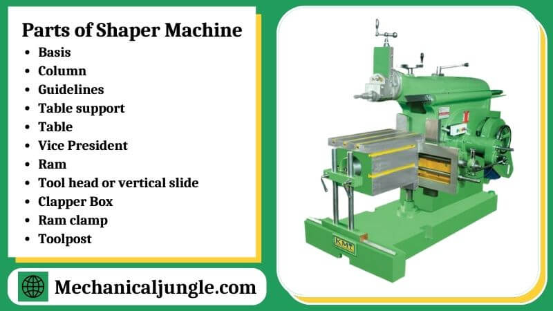
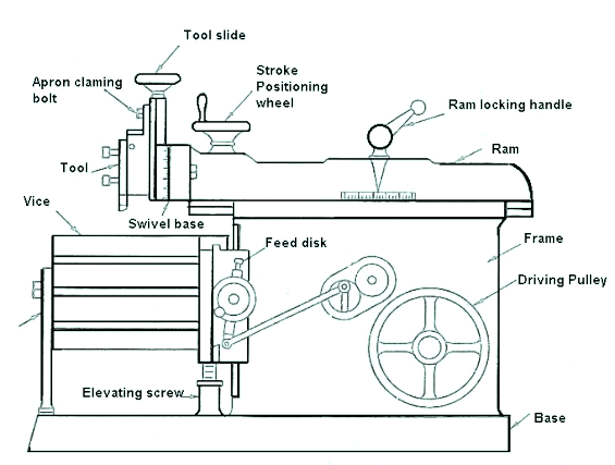
Parts of Shaper Machine:
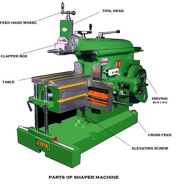
The Main Parts of the Shaper Machines Are:-
Step – 1. Basis
- As the name suggests, this is the basis of the shaper machine.
- All other parts of the machine exist on this basis.
- The base is built with cast iron capable of taking all the compressive load by various parts of the machine. The shock-absorbing capacity of the base is high.
Step – 2. Column
- The pillar is present above the base and is attached to the base.
- It is also made of cast irons and is box-like in shape.
- The column serves as the casing of drive mechanism components such as gear mechanisms, pulleys, etc., and also supports reciprocating RAM and the workforce.
Step – 3. Guidelines
- Two directions are given at the top and side of the column.
- Ram rotates on a guideway, which is present at the top of the column, and the table moves up and down in another guideway, which is present at the edge of the column.
Step – 4. Table support
- Table sliding support is present near the base in front of the table that supports the table while slidings up and down the path of the column.
Step – 5. Table
- The table is a metal body that slides up and down the direction passage of the column.
- The main function of the table is to hold the workpiece, and the vice president is placed on this table.
- The table is in the shape of the box, and the T-slots are cut on the table in such a way that the vice of any machine can be fitted on that T-slot and fit properly into it.
Step – 6. Vice President
- The vice is present on the table and is used to hold or fasten the workpiece properly.
- The vice has two jaws, one movable and the other fixed.
- One of the jaws is movable, so workpieces of different sizes can be fastened between the two jaws.
Step – 7. Ram
- Ram shaper is the main part of the machine.
- The ram is built to the left and right in the guideway of the column with cast iron and slides.
- It holds the device and gives it a reciprocating motion.
- In a crank-driven machine, the ram is attached to the rotating arm, which speeds up the ram.
- In a hydraulic driven machine, the ram is connected with a hydraulic housing that accelerates the ram.
- The single-point cutting tool is used as a tool in a shaper machine that is usually made of high speed steel or sometimes high carbon steel.
Step – 8. Tool head or vertical slide
- It can move up & down with the help of handles.
- Also, it can be rotated at any angle.
- The handles of the tool head are called the tool feed handle.
Step – 9. Clapper Box
- The Clapper Box helps the tool to fit inside the tool posts.
- The main function of the clappers box is to provide clearance for the tool in the return stroke.
- It also prevents the cutting edge from being pulled on the workpiece in the return stock and prevents tool wear.
Step – 10. Ram clamp
The ram clamp is used to determine the position of the ram.
Step – 11. Toolpost
Tool posts are used to properly place and manipulate tools. Shaper machine has two types of traversing wheels. They: –
#1. Hand traversing wheel
- Hand traversing wheels are used to move the table up and down.
#2. Crossfeed handle
- Crossfeed handles are used to feed the tool in the forward and backward direction.
- While the hand traversings wheel helps to move the table up and down, the crossfeed handle helps the table move in the cross direction.
Working of Shaper Machine:
The shopper machine operates on a quick return mechanism. It is used to shape metal or to create flat surfaces, grooves, and slots. It cuts the metals in one stroke in the backward or fifth motion, and the rest becomes useless. Shaper machine work can be described as follows.
- First, the work is fixed on the machine’s table.
- The single-point cuttings tool is mounted on a tool post located on the ram.
- Now the motor starts manually, which causes the rotating speed of the RAM by a quick return mechanism.
- When the ram is in reciprocating motions, the tool rubs the workpiece, removing unwanted material. It cuts the metal in a forward shock.
- Whereas in the return stroke, the clapper provides clearance between the tool and the workpiece, which ensures that there is no cutting in the return stroke.
- If the tool cuts the material both front and back, it eliminates the corroded surface and also causes tool wear.
Today we have discussed shaper machine parts and working. Suppose you have any questions about this article, comment and ask. If you like this article, don’t forget to share it on social networks. Subscribe to our website for more informative articles. Thanks for reading this.
Frequently Asked Questions (FAQ)
What Is a Metal Shaper Used For?
My homemade metal shaper is a tool for cutting metal from a workpiece along a linear stroke. In addition to my home-built metal lathe, I am using the shaper extensively as I build a horizontal milling machine.
Metal Shaper for Sale
Aluminum or Steel Sheet Metal Shaper for Sale from Mittler Brothers/tanner Racing Products. Shop Fabrication Tools and Metal Shapers for Sale and Shipped Nationwide.
Shaper Machine Tool
A shaper is a metal-cutting machine in which the workpiece is usually held in a vise or similar device that is clamped to a table and can be manually operated or power driven at right angles to the path of a chisel-like cutting tool with only one cutting edge held on the end of a reciprocating ram.
Shaper Machine
The shaper machine is a reciprocating type of machine basically used for producing horizontal, vertical, or flat surfaces. The shaper holds the single-point cutting tool in ram, and the workpiece is fixed on the table.
How Does a Shaper Machine Work?
A shaper machine holds the Single point cutting tool in ram, and the workpiece is fixed over the table. The ram holding the tool reciprocates over the workpiece, and metal is cut during the forward stroke called a cutting stroke. No metal cut during its return stroke is called an Idle stroke.
Shaper Machine Working
In a standard shaper, cutting takes place during the forward stroke of the ram, and the backward stroke remains idle. The forward and backward motion is obtained by the “Quick Return Mechanism.” The depth of the cut is adjusted by moving the tool downwards towards the workpiece.
Like this post? Share it with your friends!
Suggested Read –
- What Is a Synchromesh Gearbox? | Principle of Synchromesh Gearbox | Construction of Synchromesh Gearbox | Working of Synchromesh Gearbox
- Working of Constant Mesh Gearbox | What Is a Constant Mesh Gearbox? | Different Gear Ratios in Constant Mesh Gearbox | Construction of Constant Mesh Gearbox
- Difference Between Orthogonal and Oblique Cutting | Orthogonal Machining
- What Is Magneto Ignition System | How Does an Ignition System Work | How Does a Magneto Work | What Does a Magneto Do | Magneto Ignition System
- What Is Cupola Furnace? | Cupola Furnace Design । Cupola Construction | Purpose of Cupola | Working Principle of Cupola Furnace: | Advantages of Cupola Furnace | Disadvantages of Cupola Furnace | Applications of Cupola Furnace