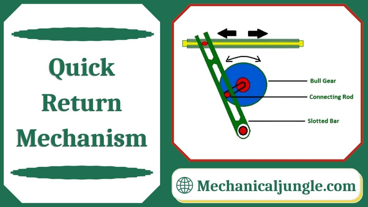
What Is the Quick Return Mechanism?
A quick return speed mechanism is used in the shaper and slotter machine in which the circular motion is converted to reciprocating motion so that the slider moves forward and backward. In the forward direction, the cutting process occurs when there is no such cutting in return.
Types of Quick Return Mechanism:
An accelerated return mechanism is a mechanism that produces a reciprocal effect so that the system has less time to return stroke when compared with the forwarding stroke.
In the quick-return mechanism, a circulars movement like the crank & lever mechanism converts to reciprocating movement, but the returns time is different from the forward moments.
In many applications, this process is used. Some of them are shaper, slotters, screw-press, mechanical drive, etc. The time required for cuttings is reduced with the help of a quick accelerating mechanism.
There are three types of quick return mechanisms:-
- Hydraulic Drive.
- Crank and Slotted Link Mechanism.
- Whitworth Mechanism.
#1. Hydraulic Drive-
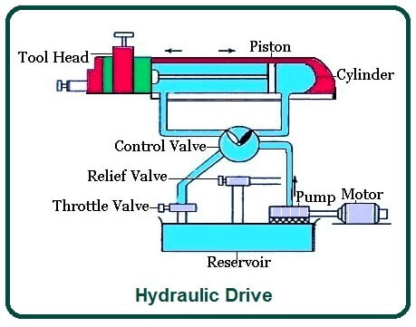
- The hydraulic drive mechanism is one of the mechanisms used in shaper machines. In this mechanism, the ram is moved back and forth by a piston rotating in a cylinder placed under the ram.
- This machine consists of a continuous discharge oil pump, a cylinder, a valve chamber, and a piston. The piston ram is fastened to the ram body.
- Hydraulic fluid is used in the hydraulic quick return mechanism to speed the ram.
Working of Hydraulic Drive:-
- In hydraulic drives, the bottom consists of a tank that holds hydraulic fluid. This tank is also known as an oil reservoir. Earlier oil used to come out of the reservoirs.
- This oil is passed through the valve chambers to the right of the oil cylinder, pressurizing the piston.
- Any oil on the left side of the piston is discharged into the reservoir through the throttle valve.
- First, the fluid in the tanks is pumped out, and this fluid passes through the passage on the right side of the cylinder. This fluid exerts pressure on the pistons, and the machine mess strokes forward.
- When the ram moves forwards, the lever changes its position & kills the overturned dog. As the lever changes its positions, the three valves attached to the lever also change their position, and the oil can now pass through the passage on the left side of the cylinder.
- After the completion of the forward stroke, the valves change their position, and the pump fluid from the reservoir now runs along the passage to the left of the piston.
- Also, the pass-through, which oil returns to the reservoir, opens and joins the right path, and the fluid on the right side of the piston reaches the reservoir.
- As the fluid moves to the left of the piston, the piston that attaches to the ram moves to the right, and a return stroke is made by the ram.
- At the end of the return strokes, another dog was hit against the lever, and the stroke changed along the direction of the lever. In this way, the forward and return strokes of Rama are repeated.
- A quick return occurs due to the difference in stroke volume of the cylinder at both ends. The volume of the left-hand side is less than the amount of the right-hand passage.
- As the pump is a continuous discharge pump, the same amount of oil will be passed on both routes. So with lower volume, the pressure n pass will be greater, and the return stroke will be fasters than the forward stroke.
- The cuttings speed can be controlled by controlling the flow of oil, which can be controlled using the throttle valve.
- When the throttle valve is lost, the additional valve is cut through the relief valve, maintaining a uniform pressure during the cutting stroke.
#2. Crank and Slotted Link Mechanism-
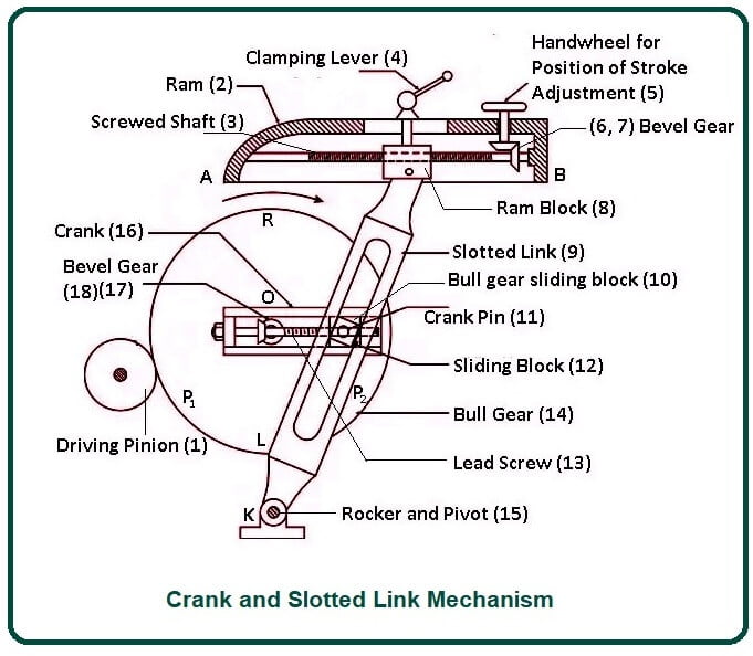
- In crank & slotted link mechanism. Power is transmitted from the bull gear by a pinion that receives its power from an individual motor.
- In a two-year system, smaller gears are called pinions, and larger gears are called bull gears.
Working of Crank & Slotted Link Mechanism:-
- The radial slide is moved to the center of the bull gear. This radial slide consists of a sliding block that fits the crank pin.
- The crank will rotate at the same speed as the bull gear rotates.
- The sliding block mounted on the crank pin is fitted to the crankpin, which is fitted within the slanted link. This slanted link is attached to the column frame, with its lower end pivoted.
- The uppers end of the sliding link is bisected and connected to the ram block by a pin.
- When the bull rotates the gear, the crankpin rotates at a uniform speed. the sliding block fastening the crankpin will rotate on the crank pin circle, and at the same time, this slider will slide up & down in the sliding link.
- As the slider moves inside the sliding link, it will provide a rocking movement to the sliding link, and this movement will provide motion by being transferred to the ram.
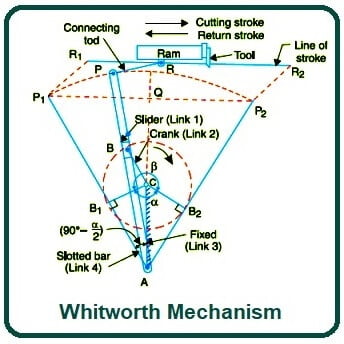
#3. Whitworth Mechanism-
- This mechanism converts rotary motion into oscillatory motion, just like the chronic and lever mechanism.
- The difference between the crank & lever mechanism and the Whitworth mechanism is that the return stroke in the Whitworth mechanism is faster than the forward stroke while the forward stroke in the crank and lever mechanism is of the same speed as the return stroke.
Parts used in Whitworth mechanism:-
- Slotted Bar.
- Slider.
- Crank – It will rotate.
- Whitworth’s quick return system is the second inverse of the slider-crank mechanism in which the crank is fixed.
- In this mechanism, the slider in the slotted bar is attached to the crank. When the cranks rotate, the slider will slide inside the slotter’s bar and oscillate the slanted bar. As the slotted bar oscillates, the ram will move forward and backward.
- This mechanism has a return stroke or, ideally, faster than a forward stroke.
- In the figure above, ap is slated bar and link 1; cd is link 2, ac which is crank, the link is 3, and link 4 is a slider.
- In this mechanism, link CD, i.e., link 2, that forms the turning pair, is fixed as shown in the figure above.
- The crank AC rotates with the same velocity at the center of A.
- A sliding block AP is connected to the crankpin on B slides with the slide bar AP and thus causes the AP to oscillate about the pivot point A. A short link pushes the speed from the pr AP to the ram, which carries the tool, and thus, forward strokes and backward strokes are achieved.
- The cranks need to rotate through an angle of (β) for the forward stroke, & it needs to rotate through the angle of (α) for the forward strokes.
- As the crank moves with homogeneous angular velocity, the time taken to cover angle α will be less than the time it takes to cover angle β. Therefore, the time taken in exchange for the stroke will be less than the time taken in the subsequent strokes. In this way, the quicks return mechanism works.
Applications of Quick Return Mechanism:
These are the following applications of the quick return mechanism:-
- It is used in the shaper machine to flatten the workpiece.
- Slotter and Planer are used the same in machines.
- It is also used in screw presses, mechanical actuators, and rotary combustion internal engines.
Advantages of Quick Return Mechanism:
These quick withdrawal mechanisms have advantages:-
- The process is automated.
- The construction of the system is not so complicated.
- It can perform operations such as cutting, leveling and slotting the workpiece.
- Idle time is reduced due to rapid return stroke.
Disadvantages of Quick Return Mechanism:
Disadvantages of the quick return mechanism are:
- In the returning strokes, there is no contact with the work, so there is no cutting, so the process takes longer to complete.
- Forward stroke takes longer than return stroke.
- It takes more power to perform the operation.
- There is friction in the slider & piston.
- This will not work continuously due to the heat generated inside the piston and wear and tear.
- Balancing the linkage is also a major problem as the device is also connected to the linkage.
FAQs on Quick Return Mechanism
What is a Quick Return Mechanism?
A Quick Return Mechanism is used in machines like shapers and slotters to convert circular motion into reciprocating motion, allowing the slider to move forward and backward. The cutting process occurs during the forward stroke, while the return stroke happens without cutting.
Why is the Quick Return Mechanism used?
The Quick Return Mechanism is used to reduce the time required for non-cutting movements, thereby increasing the efficiency of the machine. It allows faster return strokes compared to forward strokes.
What are the types of Quick Return Mechanisms?
There are three main types of Quick Return Mechanisms:
- Hydraulic Drive
- Crank and Slotted Link Mechanism
- Whitworth Mechanism
How does the Hydraulic Drive mechanism work?
In a Hydraulic Drive mechanism, the ram moves back and forth due to a piston inside a cylinder. Hydraulic fluid is used to create pressure differences that move the piston, resulting in the forward and return strokes of the ram.
What is the Crank and Slotted Link Mechanism?
The Crank and Slotted Link Mechanism involves a crank attached to a sliding block, which is connected to a slotted link. As the crank rotates, the sliding block moves within the slotted link, creating a reciprocating motion for the ram.
How does the Whitworth Mechanism differ from other types?
The Whitworth Mechanism also converts rotary motion into reciprocating motion, but it specifically provides a faster return stroke compared to the forward stroke, unlike the Crank and Slotted Link Mechanism, where both strokes occur at the same speed.
Where are Quick Return Mechanisms commonly used?
Quick Return Mechanisms are commonly used in shaper machines for flattening workpieces, slotter machines, planer machines, screw presses, mechanical actuators, and rotary combustion internal engines.
What are the advantages of using a Quick Return Mechanism?
- Automation of the process
- Simple construction
- Efficient in performing operations like cutting, leveling, and slotting
- Reduced idle time due to faster return strokes
What are the disadvantages of a Quick Return Mechanism?
- No cutting occurs during the return stroke, which can lengthen the process time
- Forward stroke is slower than the return stroke
- Higher power consumption for operations
- Friction between the slider and piston
- Heat generation and wear and tear during operation
- Balancing the linkage can be challenging
Can the cutting speed in a Hydraulic Drive Quick Return Mechanism be controlled?
Yes, the cutting speed in a Hydraulic Drive Quick Return Mechanism can be controlled by adjusting the flow of oil using a throttle valve. This allows for uniform pressure during the cutting stroke.
What components are involved in the Hydraulic Drive mechanism?
The Hydraulic Drive mechanism includes a continuous discharge oil pump, cylinder, valve chamber, piston, and ram body. Hydraulic fluid from a reservoir is used to create pressure differences for the piston movements.
How does the Crank and Slotted Link Mechanism achieve reciprocating motion?
The Crank and Slotted Link Mechanism achieves reciprocating motion by rotating the crank, which moves a sliding block within a slotted link. This movement is transferred to the ram, creating forward and backward strokes.
What is the significance of the slotted bar in the Whitworth Mechanism?
In the Whitworth Mechanism, the slotted bar holds the slider attached to the crank. As the crank rotates, the slider moves within the slotted bar, causing the bar to oscillate and drive the ram’s reciprocating motion.
How is the quick return achieved in the Whitworth Mechanism?
Quick return in the Whitworth Mechanism is achieved because the crank needs to rotate through a smaller angle for the return stroke compared to the forward stroke, resulting in a faster return motion.