
Important Point
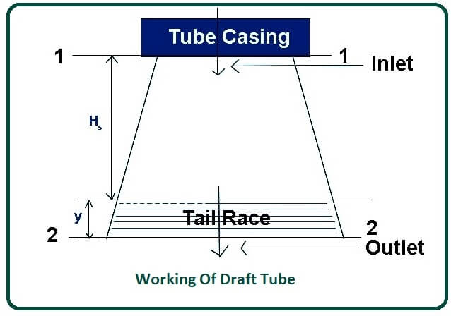
Working of Draft Tube:
- In the case of turbines such as the Kaplan turbine and Francis turbine, the head available at the inlet is generally low, so the turbine is positioned much closer to the tailrace to achieve maximum head as most of the water pressure changes to the turbine’s mechanical energy, the pressure head at the outlets of the turbine is below atmospheric pressure.
- Since the exhaust of the turbine is placed near the run of the story and the water pressure at the exit of the turbine is less than the atmospheric pressure, it can cause water backflow.
- This is because, at the exit of the turbine, the water flows from high pressure to low pressure and pressure and is lower than atmospheric pressure.
- The backflow of water causes severe damage to the turbine and its various parts and may prevent the turbine from functioning.
- Avoids this problem of backflow; a draft tube is used between the outlet of the turbine and the tailrace. The draft tube raises the water pressure to atmospheric pressure.
Applying Bernoulli’s Principle at sections 1-1 and 2-2
[ Pressures Head + Velocity Head + Elevation Head]1-1 = [Pressure Head + Velocity Head + Elevation Head ]2-2
Let,
- P1 = pressure of the fluid at section 1-1 (an inlet of a draft tube).
- V1 = velocity of the fluid at section 1-1 (an inlet of a draft tube).
Similarly,
- P2 = pressure of the fluid at sections 2-2 (outlet of the draft tube).
- V2 = velocity of the fluid at sections 2-2 (outlet of the draft tube).
- ρ = densities of flowing fluid
- g = gravitational force
- hf = loss of head (energy) in the draft tube
- Hs = verticals height of draft tube above the tailrace
- y = distance of the bottom of the draft tube from the tailrace.
- Pa = atmospheric pressure of the fluids.
( P1 / ρg ) + ( V12 / 2g ) + ( Hs + y ) = ( P2 / ρg ) + ( V22 / 2g ) + ( 0 + hf )
( P1 / ρg ) = ( P2 / ρg ) – ( Hs + y ) + ( V22 / 2g ) – ( V12 / 2g ) + hf
Pressures head at sections 2 – 2 is equal to atmospheric pressures head and distances y.
( P2 / ρg ) = ( Pa / ρg ) + y
( P1 / ρg ) = ( Pa / ρg ) + y – Hs – y + ( V22 / 2g ) – ( V12 / 2g ) + hf( P1 / ρg ) = ( Pa / ρg ) – Hs + ( V22 / 2g ) – ( V12 / 2g ) + hf
Converting the equations for our requirement (i.e., in the middles of R.H.S taking “-” commons)
( P1 / ρg ) = ( Pa / ρg ) – Hs – [ ( V12 / 2g ) – ( V22 / 2g ) – hf ]
In the above equations [ ( V12 / 2g ) – ( V22 / 2g ) – hf ] is called kinetics head.
Here [ ( V12 / 2g ) – ( V22 / 2g ) ] is the dynamics head.
From the above equation, we can write.
( P1 / ρg ) < ( Pa / ρg )
So P1 < Pa
The pressure head at the inlets of the draft tube or outlet of the turbine is less than the atmospheric pressure. So the net head on the turbine with the draft tube increases.
Also, Read: Simple Indexing in Milling Machine
Where Is the Draft Tube Used?
- The draft tube is a connecting pipe that is usually fitted at the outlet or exhaust of the turbine, which converts the kinetic energy of the water to static pressure at the outlet of the turbine.
- This helps to avoid the dissipation of the kinetic energy of the water flowing through the outlet of the turbines.
- It is usually fitted in power turbines such as reaction turbines, Kaplan turbines, or Francis turbines.
- The diameter of the draft tube is small near the inlet and large near its outlet. The outlet of the draft tubes is always submerged in water.
- The draft tube increases the pressures of the exit fluid in its kinetic energy and velocity. This increases the capacity of the turbines. It is located just below the runner and allows the flow velocity to exit from the runner.
- The materials used to make draft tubes are cast steel and cement concrete. The efficiency of a draft tube is the actual kinetic energy that is converted to static pressure.
Also, Read: What Is a Flame in Gas Welding? | Types of Flames in Gas Welding
The Efficiency of Draft Tube:
- The efficiency of draft tube Ƞd = Actual conversion of kinetic energy to pressure heat at the inlet of the draft tube.
Therefore,
- Ƞd = (Actual conversions of kinetic energy into pressure head)/(Total Kinetic energy present at inlet of the draft tubes)
- Ƞd= [ ( V12 / 2g ) – ( V22 / 2g ) – hf ] / [ ( V12 / 2g ) – ( V22 / 2g ) ]
- Actuals conversion of kinetic head into pressures head = [ ( V12 / 2g ) – ( V22 / 2g ) – hf ]
- Theoretical conversion of kinetic head into pressures head = [ ( V12 / 2g ) – ( V22 / 2g ) ]
Types of Draft Tube:
Draft tubes are mainly classified into four types, and those are:
- Conical Diffuser Draft Tube.
- Simple Elbow Draft Tube.
- Elbow Draft Tube with Varying Cross Section.
- Moody Spreading Draft Tube.
Also, Read: Open Belt Drive And Cross Belt Drive | Difference Between Open Belt Drive And Cross Belt Drive
#1. Conical Diffuser Draft Tube-
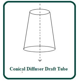
- In this type of draft tubes, the flow path is straight & divergent. This draft tube is made with mild steel plates.
- It is thin in size, and the diameter of the outlet is larger than the inlet diameter of this draft tube.
- The tapered angles of the draft tube should not be too large as it will cause separation of the flow from the draft tube wall.
- This angle should not be too small because it requires a long draft tube which causes a significant loss of kinetic energy. So the taper angle is always about 10 degrees.
#2. Simple Elbow Draft Tube-
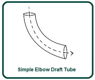
- In a simple elbow draft tube, the tube is elbow-shaped. It is mainly used in Kaplan turbines. In this type of draft tube, the cross-section area remains the same throughout the length of the draft tube.
- The inlet & outlet of the draft tube is circular. This draft tube is usually used at low head locations, and the turbine is to be placed close to the tailrace.
- This helps cut the cost of digging, and the exhaust diameter must be as large as possible to recover kinetic energy at the runner’s outlet.
Also, Read: What Is Pirani Gauge? | Working of Pirani Gauge | Construction of Pirani Gauge | Principle of Pirani Gauge
#3. Elbow Draft Tube with Varying Cross Section-
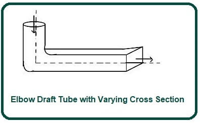
- The elbow draft tube with different cross-sections is an improvement of the simple elbow draft.
- In this type of draft tube, the inlets are circular, and the outlet is rectangular in shape.
- The horizontals portion of the draft tube is usually tilted upward to prevent air ingress from the exit end.
- The cross-section area of the type of draft tubes varies from inlet to outlet. The outlet of this draft tube is always below the tailrace.
- It is commonly used in Kaplan turbines, and the efficiency of this type of draft tube is about 70 percent.
#4. Moody Spreading Draft Tube-
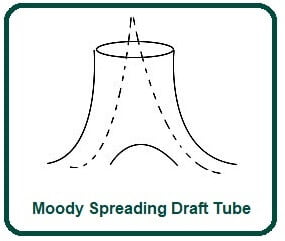
- In this type of draft tube, an outlet of the draft tube is divided into two parts. It is similar to a conical draft tube and is provided with a central core part that divides the outlet into two parts. This draft tube has one inlet and two outlets.
- This type of draft tubes is mainly used to reduce the swirling action of water.
- It is used in vertical shaft turbines. The efficiency of this type of draft tube is about 88 percent.
Also, Read: EBM Machining | Principle of Electron Beam Machining | Working of Electron Beam Machining
The Function of a Draft Tube:
- This reduces the velocity of the fluid and therefore increases the pressure of the fluid to atmospheric levels.
Advantages of a Draft Tube:
- It is one of the important components that is used to convert water into energy.
- It is found in the piping system, dam, where it is difficult to deliver mechanical work to the turbine.
- The draft tube prevents the splendor water from coming out of the runner and carries its guide water to the teller.
Applications of a Draft Tube:
- It is used to increase the surrounding pressure by a lower turbine exhaust pressure, thereby rejecting the fluid.
- So this is the observation about the draft tube; I hope I will be able to distribute my knowledge well; feel free to ask your doubts in the comments section; otherwise, you ask us directly on our community portal can.
- And don’t forget to share this stuff with your circle of friends and help them learn more about the draft tube.
Frequently Asked Questions (FAQ)
Road Draft Tube
It vents fumes from the engine back into the intake to be burned/recycled. A road draft tube went from the same hole in the valve cover down to under the passenger side toe board and simply vented those same fumes under the car.
Draft Tube
Draft Tube is a diverging tube fitted at the exit of the runner of the turbine and used to utilize the kinetic energy available with water at the exit of the runner.
Simple Elbow Draft Tube
Simple Elbow Draft Tube In a simple elbow draft tube, the tube is elbow-shaped. It is mainly used in Kaplan turbines. · The inlet & outlet of the draft tube is circular. This draft tube is usually used at low head locations, and the turbine is to be placed close to the tailrace.
Types of Draft Tube
There are mainly four types of draft tubes, and those are:
- Conical draft tube.
- Simple elbow draft tube.
- Moody spreading draft tube.
- Elbow draft tube with a varying cross-section.
Moody Spreading Draft Tube
A Moody draft tube is similar to a conical draft tube and is with a central core component that divides the outlet into two parts. There are one inlet and two exits for the draft tube. The main aim of this type of draft tube is to reduce the swirling motion of water.
The function of Draft Tube
The principal purpose of the draft tube is to convert water kinetic energy into pressure energy. To decrease the velocity of the water and to raise the pressure of the water before joining the tailrace, the pipe is used to steadily increase the cross-sectional area.
Like this post? Share it with your friends!
Suggested Read –
- Difference Between Orthogonal and Oblique Cutting | Orthogonal Machining
- Parts of Shaper Machine | What Is the Shaper Machine? | Working of Shaper Machine
- What Is a Synchromesh Gearbox? | Principle of Synchromesh Gearbox | Construction of Synchromesh Gearbox | Working of Synchromesh Gearbox
- Working of Constant Mesh Gearbox | What Is a Constant Mesh Gearbox? | Different Gear Ratios in Constant Mesh Gearbox | Construction of Constant Mesh Gearbox
- What Is Magneto Ignition System | How Does an Ignition System Work | How Does a Magneto Work | What Does a Magneto Do | Magneto Ignition System