Important Point
What Is Vane Pump?
A Vane pump is a positive displacement pump used to increase the pressure of the flowing fluid by the use of a vane that is mounted on a rotor. This pump can be used to flow fluid from one point to another at high pressure. Van pumps may have variable lengths of vans or tensioned to maintain the van’s contact with the pump wall as the vans rotate. The vane pumps were invented by Charles C. Barne in 1874.
Modern vane pumps have field contact between the rotor and the stator rather than line contact. Vane pump is commonly used in automobiles, power steering of vehicles, & are also used in air conditioners.
The vane pump is not good for highly viscous fluids. Vane pumps can handle medium viscous fluids, and they are less viscous fluids such as LP. Excellent for handling gases, ammonia, solvents, alcohol, etc. It is also used to convert high-pressure gas to low-pressure gas.
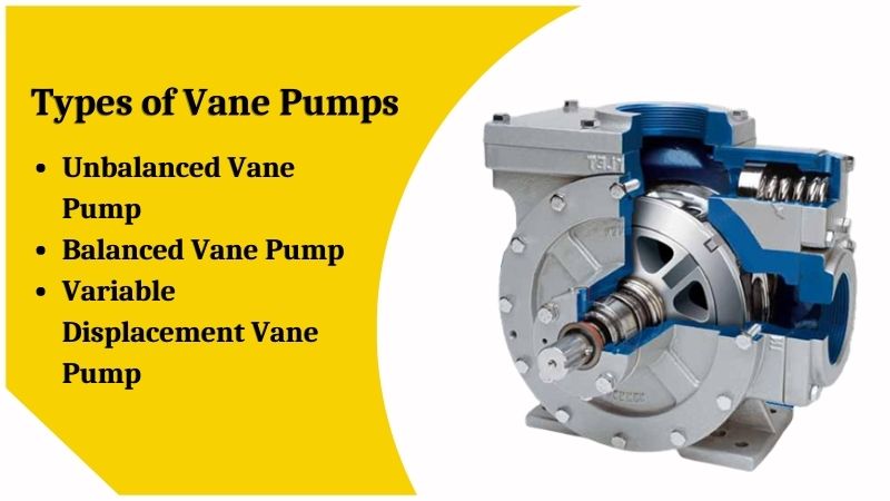
Types of Vane Pumps:
There are mainly three types of vane pumps:
- Unbalanced Vane Pump
- Balanced Vane Pump
- Variable Displacement Vane Pump
#1. Unbalanced Vane Pump
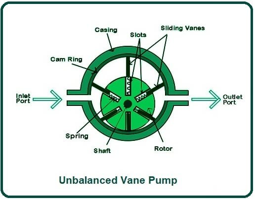
Unbalanced vane pumps are the regular vane pump that you have read in this article. It consists of a cylindrical rotor mounted on an offset inside a circular casing. This means that the center of the cylindrical rotor and the center of the casing is not coincidental. The center of the casing and the centers of the rotor are at some distance. There is no leakage between the vane tips and the casings.
A side thrust is made on the rotor shaft due to the difference in pressure between the inlet and outlet port. Due to the sides thrust on the rotor shafts, the bearing’s life is reduced. Due to the pressure difference in the inlet and outlet port, this vane pump is called an unbalanced vane pump. In balanced vane pumps, there is no side thrust on the rotor shaft.
#2. Balanced Vane Pump
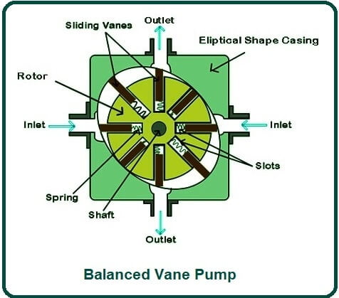
In balanced vane pumps, the casing is elliptical in shape. The center of the rotor and elliptical casing is the same, and no offset is used. For equilibrium, two inlets and two outlets are provided, due to which no pressure difference is created between the inlet and the outlet.
Two inlets are present on opposite sides of each other, and two outlets are present on opposite sides of each other. Due to thises type of arrangement of inlets & outlets, equal and opposite thrust is balanced, and therefore no side thrust is experienced by the rotor shaft.
A balanced pump gives better service and longer life. The pocket size between the two vans increases when moving from the outlet to the outlet, and the pocket size decreases when moving from the inlet to the outlet. Therefore the inlet port has suction, and the outlet port has a delivery.
#3. Variable Displacement Vane Pump
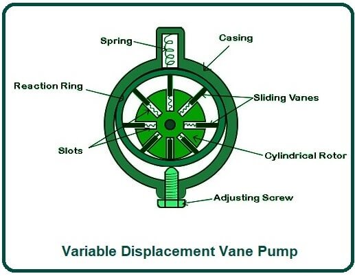
In a variables displacement vane pump, the pocket-size can be varied. Due to different pocket sizes, the discharge from the outlet varies. In this variable displacement vane pump, the casing is not in direct contact with the casing.
A ring is provided between the casing and the pane, and this ring is called the reaction ring. On one side, the feedback ring is connected with the adjustment screw, and on the other side, it is connected with a spring.
The adjusting screw is used to separate the pocket size of this pump. By turning the adjustment screw, the reaction ring can be moved upward or downward. By moving the reaction ring up or down, the offset between the reaction ring center and rotor center.
As the offset change, the pocket-size also changes, & hence the discharge from the pump changes.
Working of Vane Pump:
First, power is provided to the shafts of the pump using an electric motor. After providing power, the shaft starts rotating, & the rotor which is mounted on the shaft also starts rotating. When the rotor rotates, the sliding vans present in the slot of the rotor experience a centrifugal force that is radially directed outward.
Due to the centrifugal forces on the sliding vane, the vans move outward, and the spring that connects the rotor and vane expands. Then the springs expand, and the sliding vans establish contact with the cam-ring, and this contact is established until the rotor rotates.
When the vane reaches a position where the distance between the rotor shaft and the casing is short, the spring of the vanes is compressed to maintain contact with the cam-ring. In this case, the area between the two adjacent vans and the casing is also smaller, i.e., the pocket size is smaller.
Similarly, when the vane reaches a position where the distances between the rotor shaft and the casing are large, the spring of the vanes expands to maintain contact with the cam-ring. In this case, the area between the two adjacent vans and the casing is also larger.
When the rotors rotate continuously, after some time, suctions are formed in the inlet port, which causes the fluids to be sucked into the inlet port.
The fluid that is sucked through the inlet is trapped between two adjacent vans, & as the vanes are always in contact with the cam-rings, the trapped fluid rotates along with the two adjacent vans.
While moving from the inlet ports to the outlet port, fluid experiences a centrifugal force that increases the pressure of the fluid, & this high-pressure fluid is transported through the outlet port to the required area.
Near the inlet of the vane pumps, the space between the two adjacent vans increases due to the increasing distance between the shaft and the casing. As the space between two adjacent vans increases, a vacuum is created near the inlet of the vane pump. Due to the vacuum created, suction starts, and fluid is drawn from the pump’s inlet.
After that, as the rotors continue to rotate, the compression of the fluid continues to rotate, the space between the adjacent vans begins to decrease, i.e., the pocket size decreases. As the pocket size decreases, the fluid volume decreases, and the entangled fluid becomes narrower, and the fluid pressure increases. After that, the high-pressure fluids are discharged from the outlet of the vane pump.
Components of Vane Pump:
#1. Casing
The cover vane is the outer covering of the pump. All other components of the vane pumps are present inside this casing.
The wrapper has two casing:-
Inlet port:- Fluid enters the pump through this inlet port.
Outlet port:- The high-pressure fluid exits the pump through the outlet port.
#2. Shaft
Inside the vane pump is a shaft that is connected to a prime mover.
A rotor is mounted on the shaft, & it rotates using the power of the prime movers.
#3. Rotor
The rotor of the vane pumps has slots that are equally spaced around the rotor.
This rotor has various radial slots.
#4. Sliding Vanes
Slot vans are present in the slot of the rotor. Sliding vans move freely inside the rotor slots. The sliding vans are rectangular-shaped and are attached using a spring with the rotor.
#5. Cam Ring
The cam ring is present on the inner wall of the casing.
Also, Read: What Are Cutting Fluids? | Types of Cutting Fluids | Uses of Cutting Fluids | Selection of Cutting Fluid
Working Principle of Vane Pump:
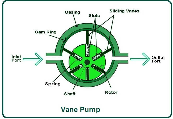
The schematic of the vane pump’s working principle is shown in the figure. Vane pumps generate a pumpings action by tracking the vane along the casing wall. In the vane pump, the rotor is connected to the prime mover via a shaft. Vans are located on a slotted rotor.
The rotor is placed eccentrically inside a cam ring, as shown in the figure. The rotor is sealed in the cam by two side plates. When the prime mover rotates the rotors, the van is thrown outward due to centrifugal force—Van tracks along the ring.
This provides the fluid with a tight hydraulic seal that is higher at higher rotation speeds due to higher centrifugal force. This produces suction cavities in the ring as the rotor rotates. This creates a vacuum at the inlet, and, therefore, the fluid is pushed into the pump through the inlet.
The fluid is carried around the outlet by the vanes, by which the fluid is expelled by retreating. The efficiencies of the pump depending on the eccentricity, expansion of the vanes and the width of the vanes, and the rotor speed. It may be noted that the fluid will not flow when eccentricity is zero.
These pumps can handle thin fluids (low viscosity) at relatively high pressures. However, these pump is not suitable for high-speed applications and for high-viscosity liquids or liquids carrying certain viscous particles.
Also, Read: What Is a Hacksaw? | Parts of Power Hacksaw | Driving Mechanism of Power Hacksaw | Working of Power Hacksaw
Advantages of Vane Pump:
- Vane pumps are self-priming, strong, and provide continuous delivery at a fixed speed.
- They provide uniform discharge with negligible vibrations.
- Their vans are self-compensating for wear, and vans can be easily replaced.
- These pumps do not require a check valve.
- They are light in weight and compact.
- They can handle liquids containing vapors & gases.
- Volumetric and overall efficiencies are high.
- Discharge is less sensitive to changes in viscosity & pressure variations.
- It can handle low viscosity liquids at high pressures.
- It can dry run for short periods.
- This pump develops a good vacuum.
- A balanced pump bearing eliminates side loads, and therefore higher operating pressures can be used.
Disadvantages of Vane Pump:
- Relief valves are required to protect the pumps in the event of a sudden stop of delivery.
- They are not suitable for abrasive liquids.
- They require good sealing.
- They require good filtration systems, and foreign particles can severely damage the pump.
- It has a complex design.
- It is unsuitable for high viscosity liquids at high pressures.
- They are fixed displacement pumps.
- The design is more complex.
- The manufacturing cost is higher as compared to the unbalanced type.
Application of Vane Pump:
This pump has various applications for the pumping of the following fluids:
- Aerosol and Propellant
- Aviation Services – Fuel Transfer, Deicing
- Auto Industry – Fuel, Lube, Refrigeration Cooling
- Bulk transfer of LPG and NH3
- LPG cylinder filling
- Alcohol
- Refrigeration – Freons, Ammonia
- Solvent
Frequently Asked Questions (FAQ)
What Is Vane Pump?
A vane pump is a self-priming positive displacement pump providing constant flow at varying pressures. Operation is via a motor connected to a gearbox, as typically, the maximum rpm is 900. The pump is fitted with a relief valve to prevent the pump from building to a pressure that may damage the pump.
Types of Vane Pumps
There are mainly three types of vane pumps:
- Unbalanced Vane Pump
- Balanced Vane Pump
- Variable Displacement Vane Pump
Rotary Vane Pump Working Principle
The rotary vane vacuum pump works on a positive-displacement pumping principle. The design consists of a rotor, which is mounted eccentrically inside a cylindrical housing or stator. Blades, mounted inside the rotor, move in and out due to centrifugal force following the internal surface of the housing.
Working of Vane Pump
A vane pump uses a rotating cylinder with slots (or rotors) housing a series of vanes that rotate inside the cavity. The rotor is offset in a casing bore so that when rotated, the vanes slide in and out. This creates expanding and contracting volumes that move liquid through the pump.
Parts of Vane Pump
The unit consists principally of a ported body and cover, a drive shaft supported by two ball bearings, a pumping cartridge, and a pressure plate. Components of the pumping cartridge are an elliptical cam ring, a slotted rotor splined to the drive shaft, and twelve vanes fitted to the rotor slots.
Like this post? Share it with your friends!
Suggested Read –
- Cutting Fluids
- What Is a Hacksaw
- Types of Gear Pumps
- Types of Dial Indicators
- Refrigeration System Components
- Domestic Electrolux Refrigerator | Different Components of Domestic Electrolux Refrigerator
- Types of Angle Plates | Box Angle Plate of Angle Plate | Swivel Angle Plates of Angle Plate | Cast Iron T-Slotted Angle Plate of Angle Plate
- What Is Wilson-Hartnell Governor? | Wilson Hartnell Governor | Construction of Wilson Hartnell Governor | Working of Wilson Hartnell Governor
- Cochran Boiler | Cochran Boiler Working | Working Principle of Cochran Boiler | Applications of Cochran Boiler | Advantages & Disadvantages of Cochran Boiler
- What Is Cupola Furnace? | Cupola Furnace Design । Cupola Construction | Purpose of Cupola | Working Principle of Cupola Furnace: | Advantages of Cupola Furnace | Disadvantages of Cupola Furnace | Applications of Cupola Furnace