Important Point
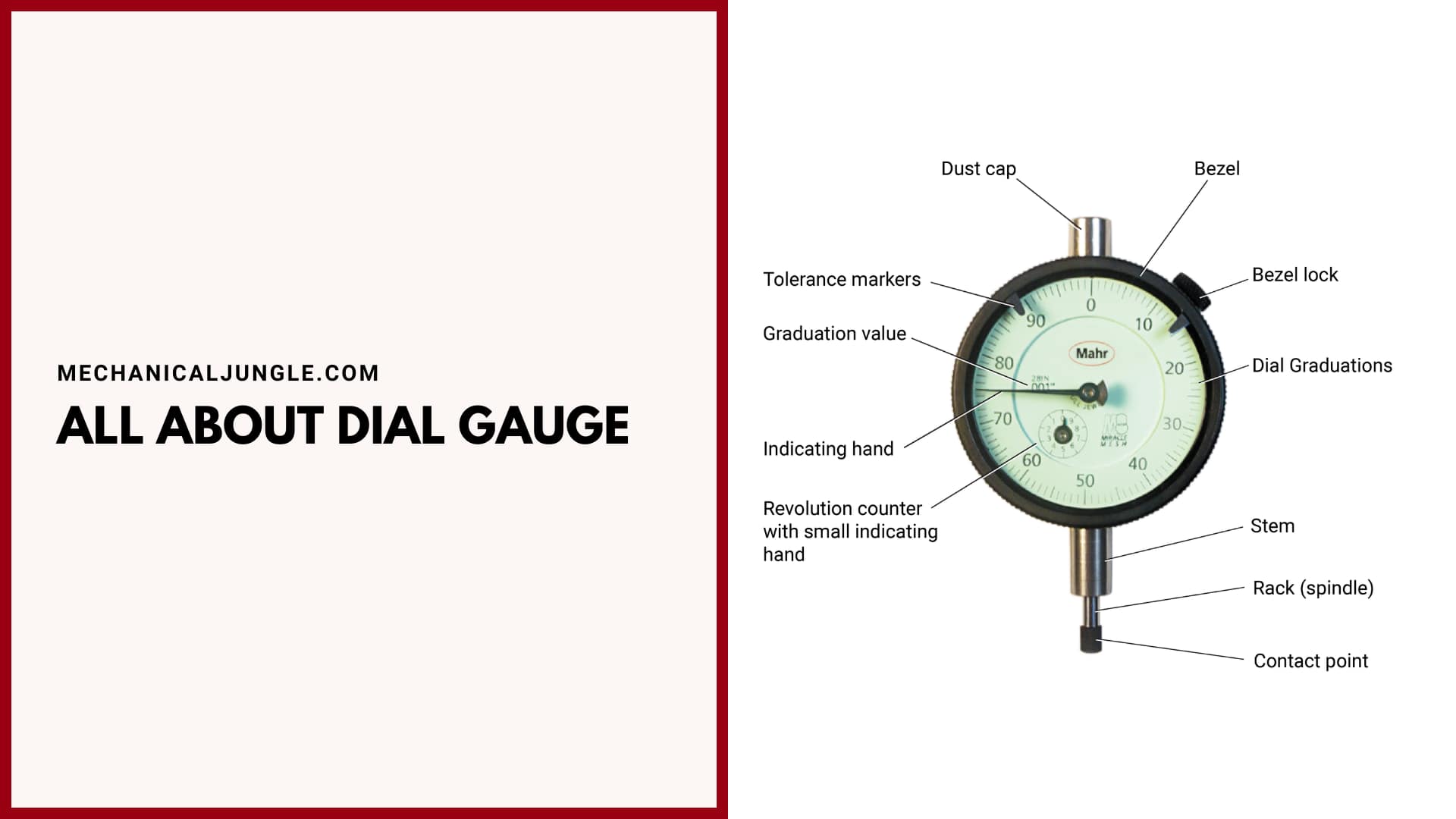
What Is Dial Gauge?
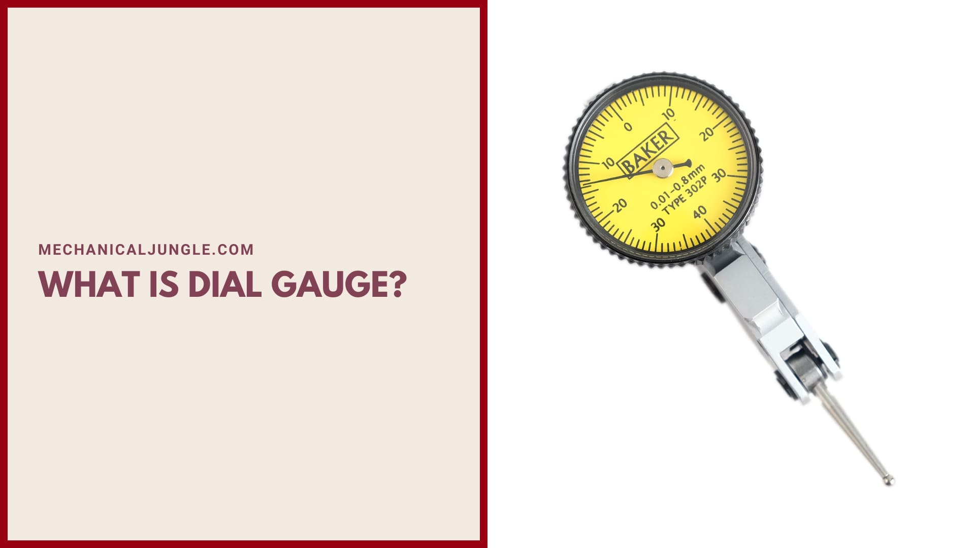
Dial gauges are used to measure the flatness and inclination of objects. It is used to check round bar roundness. It checks the flatness of an object as compared to the flatness of the standard object. In the mechanical field, dial gauges are used to check the flatness and alignment of various jobs and workpieces.
It very easy’s to use as compared to other devices like Vernier calipers, micrometers, etc.This dial gauge is based on the principles of “rack and pinion.” The dial gauge can measure up to a minimum of 0.01 mm readings. Therefore its lowest count is 0.01 mm.
Also, Read: What Is Mcleod Gauge? | Parts of Mcleod Gauge | Principle of Mcleod Gauge | Working of Mcleod Gauge
Parts of Dial Gauge Indicator:
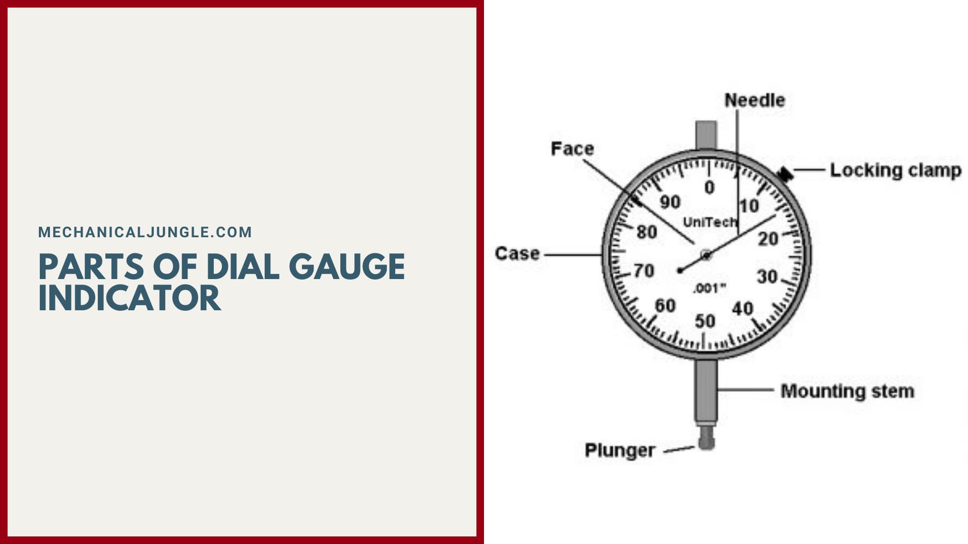
#1. Case
There is a metal casing which is the outermost part of the dial gauge.
#2. Graduated Scale
Inside the casing, graduated scales are present, marking various readings.
#3. Pointer
A Pointer exists that indicates the measured value on the graduated scale.
#4. Small Dial Gauge
This small dial gauge is present insides the dial gauge. It also has graduation. This small dial gauge has reverse reading. The readings of small dial gauges can be straight or reverse depending on the mechanism used in the gear train for the movements of the pointer to the small dial gauge.
#5. Small dial pointer
There is a small indicator that points to the measured value at the graduation of the small dial indicator. It is also called a shorthand indicator.
#6. Stem
The plunger or spindle moves up & down inside this stem.
#7. Contact Point
This contact point will have contacts with the surface & will help in the motion of the plunger. When the pointer of the external pointer completes its revolution, the pointer of the smaller pointer wills move from 0 to 1, i.e., the smaller dial pointer will show 1 mm when this larger pointer will exceed 100 reading in the larger dial pointer.
When the external pointer completes its ten rotations, the pointer of the smaller indicator will return to zero. The small dial gauges are very helpful in taking a reading.
Also, Read: What Is Pirani Gauge? | Working of Pirani Gauge | Construction of Pirani Gauge | Principle of Pirani Gauge
The Internal Arrangement of Dial Gauge:
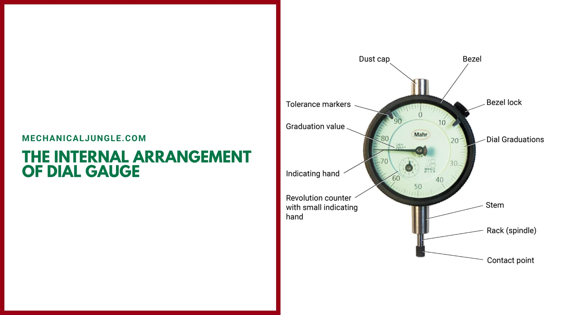
In the internal part of the dials gauge, there is a rod, & in this rod, there is a rack cut on this rod. This rack is connected to a smalls gear S1, & this small gear S1 is attached to the big gear G0, & both have the same axis.
This small pinion is also connected to another’s big gear, G1. If the small gear S1 takes ten rotations, then the big gear G1, which is connected to the small gear S1, will complete one rotation in the opposite direction.
Now, this bigs gear G1 is also connected to another’s small gear, S2, which is the gear of the outer dial pointer, & this small gear S2 is attached to a big gear G2, & both have the same axis. Thises big gear G2 is connected to a helical spring.
The main function of the helical springs is that it stores the rotational energy of the gears when the gears rotate.
These helical springs are used to reset the positions of the gear & the pointers. When the measurements are completed, the helical spring transfers the stored energy to the connected gear, & all the gears move in the reverse directions one by one & reach their initial position. Also, the rod moves to its initial positions.
Working of Internal Parts:
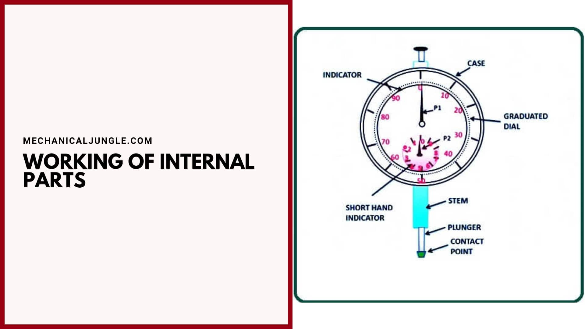
When the dial gauge is placed on top of a workpiece, the dial gauge rod moves upward, and the racks cut on it also move. The small gear S1 that attaches to the rack on the rod starts rotating. When the rod moves upward, the small gear will rotate clockwise.
This smalls gear S1 is connected to a large gear G1. This larger gear controls the G1 pointer P2, which is a pointer to the smaller dial gauge. When the smaller gear S1 rotates clockwise, the larger gear G1 will rotate in the anti-clockwise direction, and the pointer P2 connected to the larger gear G1 will rotate in the anti-clockwise direction.
G1 as this big gear An anti-clockwise direction will rotate, then the outer gear’s small gear S2 will rotate clockwise, and so the outer dial P1‘s pointer will rotate in the clockwise direction. In addition, the larger gear G2 will also rotate in a clockwise response.
Now this larger gear is connected to the G2 helical spring, and the helical spring will rotate in an anti-clockwise direction and accumulate rotational energy; and when the work is completed, the helical spring will give its energy backs to the gear, and the gears and pointers to their initial position Will come back As all gears will move in the opposite direction. So the racked rod will also move upward and return to its initial position.
Least count of Dial Gauge Indicators:-
100 lines reading in outers scale = 1mm = 1 full rotations on outer scale
Therefore, least count = 1 rotation on main scale / No of the division moved on the dial scale.
Now,
1 Rotation On Main Scale = 1mm
No. of the division moved on dial scales = 100
Hence, Least Count = 1mm /100 = 0.01mm.
How to Take a Reading on Dial Gauges?
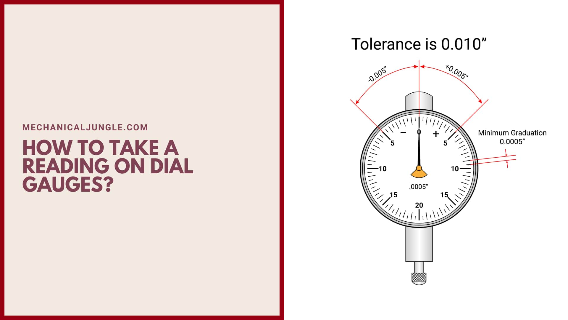
Suppose we use a dial gauge to measure the flatness of the workpiece. When we use a dial gauge to measure the flatness of the workpiece, it shows some variation. The small dial gauge indicates a reading of slightly more than three (3).
First, we will focus on the reading of the small dial indicators. We will take the only completes the reading of the small indicator. So, if reading is slightly more than three, then we will only read three and ignore the rest.
When the larger dial pointer completes a full rotation, the smaller dial pointer will move a unit that is equal to 1 mm. After taking the readings of the small dial indicator, the readings of the external dial are taken. Explain that the external dial indicator has a reading of 42.
After reading both the indicators we calculate the variations in mm using this formula:
Formula for variations (in mm) = short dial reading + (external dial reading x least count)
Now we have to assume,
Variation = 3 + (42 x 0.01)
= 3.42 mm
This is an accurate reading of surface variation using a 3.42 mm dial gauge indicator.
Types of Dial Indicators:
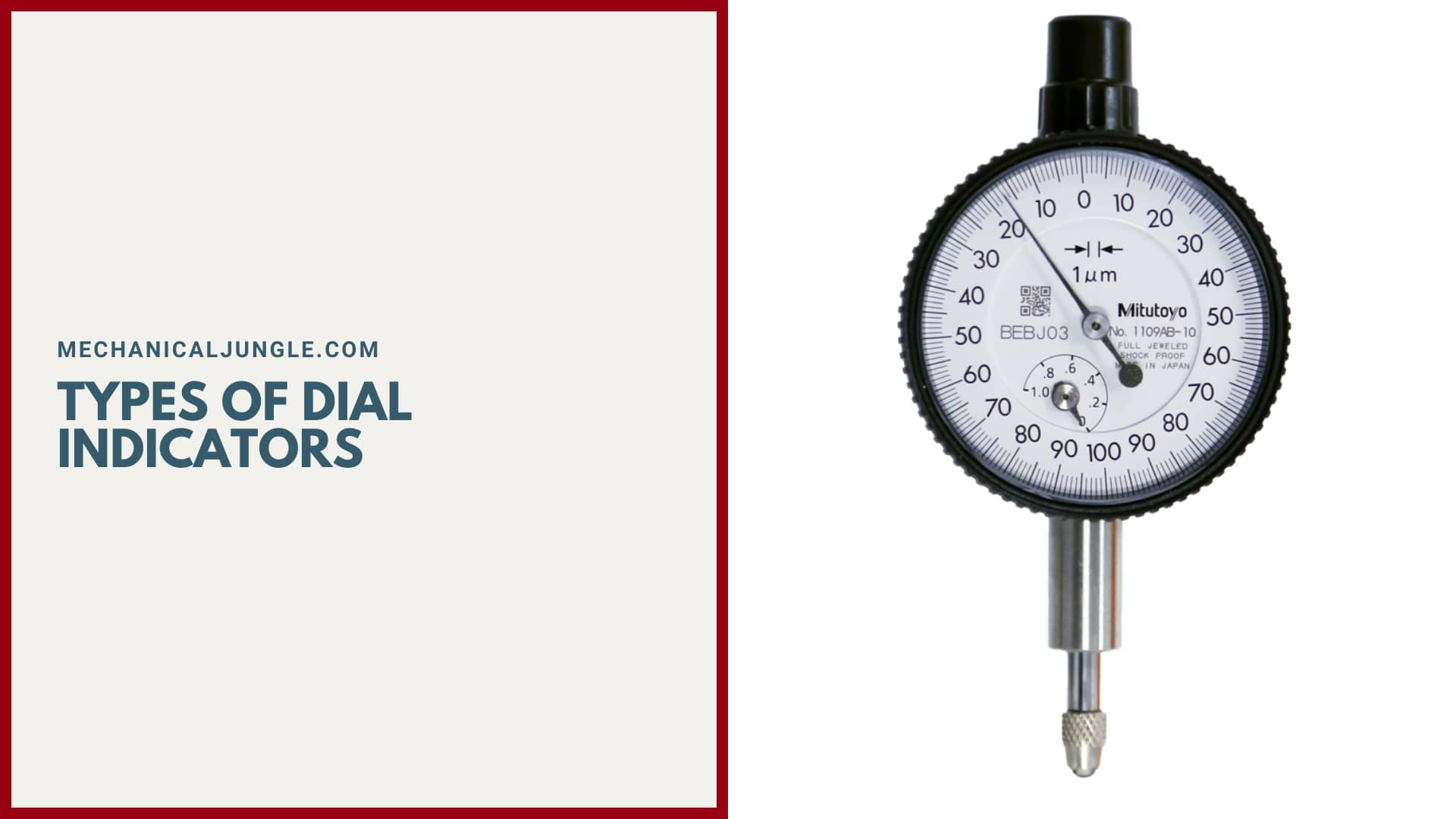
Types of Dial Indicators Many different types of dial indicators exist, differentiated by factors such as their size, connection method, & the type of information on their faces.
- Balanced reading dial indicator.
- Continuous Dial Indicators.
- Reversed Balanced Dial Indicators.
- Reversed Continuous Dial Indicators.
- Plunger Dial Indicator.
- Lever Dial Indicator.
#1. Balanced Reading Dial Indicators
Balanced reading dial indicators are named in such a way that the information on the face of the dial is organized. Figures are printed on the face of this dial running in two directions starting from a zero in the center. Often, positive numbers are depicted to the right of zero and negative numbers to the left.
#2. Continuous Dial Indicator
The constant number dial indicator does not have two sets of numbers depicted on the balanced reading dial indicator. On this type of dial indicator, the figures move in one direction without pauses and without any separation.
#3. Reversed Balanced Dial Indicators
Reversed Balanced Dial Indicator is named because they have the same basic positive & negative scales on each side of a zero, but positive numbers are on the left and negative are on the right.
#4. Reversed Continuous Dial Indicators
Reversed Continuous, or Counter-Clockwise, Dial Indicators are similar to Continuous Dial Indicators except that the number moves in the opposite direction.
#5. Plunger Dial Indicator
The Plunger Dial Indicator also has a clock-like face but features the rider on one of their sides. A common use for plunger dial indicators is to measure the work of injection molding machines. The mechanism that allows this type of dial indicator to work is a rack and pinion, which changes the linear thrust of the rider in rotary motion for the dial.
#6. Lever Dial Indicator
The specialty of lever dial indicators is their lever and scroll mechanisms, which cause the stylus to move. These types of dial indicators are more compact and easier to use than plunger-type dial indicators and are therefore often used.
Also, Read: Parts and Functions of Grinding Machine | Grinding Machine | Grinding Machine Types
Applications of Dial Gauge:
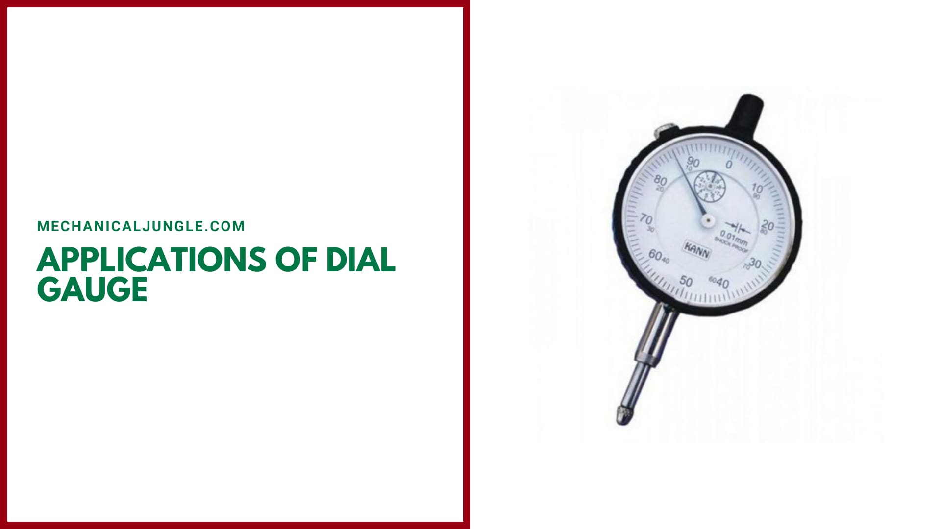
Here, the different Applications of dial gauge are as follows:
- I am comparing two heights or distances between narrow limits.
- To determine the errors in the geometrics form, such as ovality, roundness, and taper.
- For taking accurate measurements of deformations such as intension and compression.
- To determine position errors of surface such as parallelisms, squareness, & alignment.
- To check the alignments of lathe centers by using a suitable, accurate bar betweens the centers.
- To check the trueness of milling machines arbours & to check the parallelism of shaper arm with table surface or vice.
Advantages of Dial Gauge:
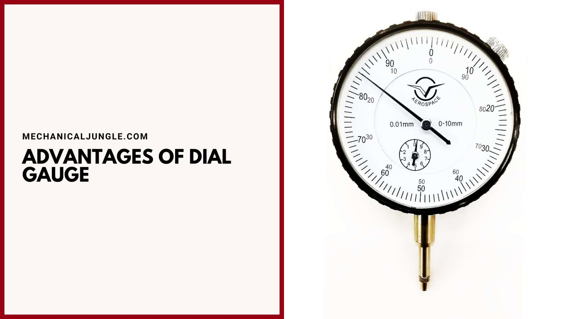
Here, the different Advantages of dial gauge are as follows:
- The size of the dial gauge is very small & compact, so it can be used easily in mass production.
- Dial gauges can be used to measures the amounts of tappers in round objects easily.
- It is the most flawless tool in takings linear measurements.
Disadvantages of Dial Gauge:
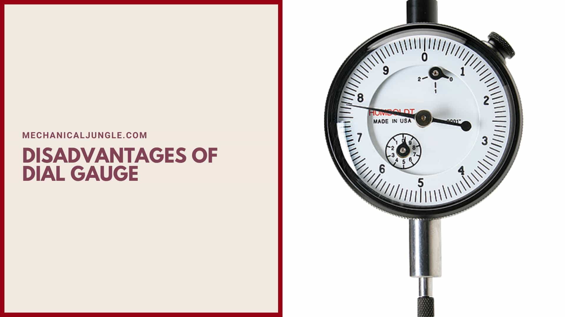
Here, the different Disadvantages of dial gauge are as follows:
- The precision of the dial gauges is often lost due to the vibration of machinery.
- The main disadvantage of the dial gauges is parallax error. ( Parallax error: Parallax error occurs when the measurements of an object’s lengths are more or less than the true lengths because of your eye being positioned at an angle to the measurement’s markings. )
- Due to space constraints, the tools are needed to be installed at an angle, due to which the accuracy of the devices is lost.
Frequently Asked Questions (FAQ)
Dial Guage
Dial Indicator with Magnetic Base Holder Fine Adjustable Long Arm 0-10mm Tester Gage Gauge 0.01mm. 4.4 out of 5 stars 132 · Currently unavailable.
Parts of a Dial Indicator
Internal parts of the dial indicator consist of several gears, rack, pinions, plunger, and springs. Let’s focus on the picture.
How to Use a Dial Indicator?
You do this by rotating the outer dial to the position of the zero mark just opposite the needle, no matter where it is pointing. Once the indicator is zero, you can measure it by rotating the relevant part. The indicator will show the movement as positive or negative.
Dial Gauge Indicator
Dial indicators are precision instruments used to measure short distances and angles. These micrometre-type instruments indicate a reading by a needle moving into the graduation on a dial face. A plunger on the indicator moves in and out of its body and rotates the measuring needle.
Dial Indicator Use
Dial indicators are one of the primary measuring tools used in precision engine building. They are typically used to measure deck clearances, crankshaft thrust and straightness, lifter travel and other measurements that involve the distance between two surfaces or small amounts of component travel.
Dial Indicator Measures
Dial indicators typically measure ranges from 0.25 mm to 300 mm (0.015in to 12.0in), with graduations of 0.001 mm to 0.01 mm (metric) or 0.00005in to 0.001in (imperial/customary).
How to Read Dial Indicator?
Dial indicators or dial gauges are nifty tools that make quick work of accurately measuring angles or distances between two flat surfaces by measuring points on a three-dimensional surface that is rarely possible with the naked eye. In order to obtain an accurate reading from the dial indicator, the modus operandi consists in determining the position of the leading surface of the dial gauge head with a scale marked on its body.
Typically, lines are marked on the body, with each number representing a step of 1 cm. Also, there are 10 numbered lines in the middle of the numbered lines where each numbered line represents 0.1 cm.
Small Dial Indicators
Discover the best Dial Indicators in Best Sellers. Find the top 100 most popular items in Amazon Industrial & Scientific Best Sellers.
Uses and Applications of Dial Gauges in Mechanical Engineering
Engineers use dial indicators for workpiece alignment in various machines including, but not limited to, milling machines, lathe machines, grinding machines, and EDM. Dial gauge indicators find significant application in automotive disc brakes where they are used to check lateral run-out.
Calibration and Maintenance of Dial Gauges for Optimal Performance
Calibration and maintenance are essential for ensuring the optimal performance and accuracy of dial gauges. Regular calibration confirms the accuracy of the gauge, while proper maintenance helps prevent damage and prolongs its lifespan. Here are some guidelines for calibrating and maintaining dial gauges:
Calibration:
- Calibration Interval: Determine the appropriate calibration interval based on the gauge’s usage frequency, manufacturer’s recommendations, and industry standards. Typically, annual calibration is recommended, but more frequent calibration may be necessary for gauges used in critical applications.
- Calibration Standards: Obtain calibrated reference standards that cover the range of measurements required for your dial gauge. These standards should have a higher accuracy than the gauge being calibrated.
- Calibration Procedure: a. Set up a controlled environment with stable temperature and humidity to minimize measurement variations. b. Place the reference standard in the same position and orientation as when measuring with the dial gauge. c. Position the dial gauge’s contact point on the reference standard and take multiple readings at different points. d. Compare the readings with the known values of the reference standard. e. Adjust the gauge if necessary, following the manufacturer’s instructions or using calibration mechanisms provided. f. Repeat the process at various measurement points within the gauge’s range.
- Calibration Certificate: After calibration, obtain a calibration certificate from an accredited calibration laboratory. The certificate should include details such as the gauge’s identification, calibration dates, measured values, and uncertainty of measurement.
Maintenance:
- Cleaning: Regularly clean the dial gauge to remove dirt, dust, and contaminants that can affect its performance. Use a soft cloth or brush to gently wipe the gauge’s surface and ensure that the contact point moves freely.
- Lubrication: Apply a small amount of lubricant to the moving parts of the dial gauge, following the manufacturer’s recommendations. This helps maintain smooth operation and prevents wear.
- Inspection: Periodically inspect the gauge for any signs of damage, wear, or misalignment. Check for bent or damaged contact points, cracked or scratched glass, loose components, or any abnormalities in the readings. Address any issues promptly or send the gauge for repair if necessary.
- Storage: When not in use, store the dial gauge in a protective case or box to prevent damage from dust, moisture, or accidental impacts. Avoid exposure to extreme temperatures or corrosive environments.
Top-Rated Manufacturers of High-Quality Dial Gauges
- Best Overall Dial Indicator—Mitutoyo 513-402-10E Dial Indicator.
- Best Clamp Base Dial Indicator—Türlen Disc Brake Rotor and Ball Joint Runout Gauge Set Dial Indicator.
- Best Adjustable Long-Arm Dial Indicator—Qnkaa Dial Indicator.
- Best Budget Dial Indicator—WEN 10702 Dial Indicator.
Benefits of Using Digital Dial Gauges in Metrology
Digital dial gauges, also known as digital indicators or electronic indicators, offer several advantages over traditional mechanical dial gauges in metrology and precision measurement applications. Here are some benefits of using digital dial gauges:
- Increased Accuracy: Digital dial gauges provide higher accuracy compared to mechanical dial gauges. They often have a higher resolution, allowing for more precise measurements. The digital display eliminates reading errors associated with parallax or misinterpretation of analog dial graduations.
- Digital Readout: Digital dial gauges feature a clear and easy-to-read digital display that directly shows the measurement value. This eliminates the need for visual estimation or interpretation of analog needle positions, resulting in faster and more accurate readings.
- Data Output and Recording: Many digital dial gauges come equipped with data output capabilities, such as USB, RS-232, or wireless connectivity. This allows for direct integration with computer systems, data loggers, or quality control software, enabling automated data recording, analysis, and documentation.
- Preset and Tolerance Functions: Digital dial gauges often include preset and tolerance functions, allowing users to set target values and tolerance limits. The gauge can then indicate whether the measured value falls within the acceptable range, simplifying quality control processes and reducing human error.
- Multiple Units and Measurement Modes: Digital dial gauges typically offer flexibility in units of measurement, allowing users to switch between metric and imperial units as needed. They may also offer various measurement modes, such as absolute, incremental, or differential, expanding their versatility in different measurement scenarios.
How to Use a Dial Gauge for Metrology?
- Set the point on the shaft.
- Slowly turn the shaft by hand to find either the highest or lowest point.
- Set the zero to that point.
- Turn the shaft again, to see the largest reading. The result is called ‘TIR’, or Total Indicator Runout.
Dial Gauge Use
Dial gauge or also known as a dial indicator, is a comparison measuring instrument (comparator). This tool is used to measure a workpiece’s flatness of surface, roundness, runout, and so on. The working principle of the dial gauge is dependent on the movement of the spindle.
Dial Gauge Is Used to Measure
Dial gauges are measuring instruments that can accurately measure minute lengths and displacements.
Dial Gauge Types
- Dial indicators in which the spindle is parallel to the dial face.
- Dial indicator in which the spindle is perpendicular to the dial face.
- Dial indicators in which the measuring contact member is a lever.
How to Read Dial Gauge?
- Set the point on the shaft.
- Slowly turn the shaft by hand to find either the highest or lowest point.
- Set the zero to that point.
- Turn the shaft again, to see the largest reading. The result is called ‘TIR’, or Total Indicator Runout.
Dial Gauge Uses
Dial gauges are measuring instruments that can accurately measure minute lengths and displacements. Unlike other measuring instruments that directly measure numerical values, they are used for measuring the difference compared to a reference or correcting parallelism.
Dial Indicator Parts and Functions
- Case: the outer part of the dial gauge.
- Lock: serves to lock the pointer needle in a certain position when reading the measurement results.
- Long pointer (long needle): indicates the measured value on the scale.
Like this post? Share it with your friends!
Suggested Read –
- Parts of a Disc Brake
- Adjustable Angle Plate
- Babcock Wilcox Boiler
- Different Types of Springs
- Domestic Electrolux Refrigerator | Different Components of Domestic Electrolux Refrigerator
- Types of Angle Plates | Box Angle Plate of Angle Plate | Swivel Angle Plates of Angle Plate | Cast Iron T-Slotted Angle Plate of Angle Plate
- What Is Wilson-Hartnell Governor? | Wilson Hartnell Governor | Construction of Wilson Hartnell Governor | Working of Wilson Hartnell Governor
- Cochran Boiler | Cochran Boiler Working | Working Principle of Cochran Boiler | Applications of Cochran Boiler | Advantages & Disadvantages of Cochran Boiler
- What Is Cupola Furnace? | Cupola Furnace Design । Cupola Construction | Purpose of Cupola | Working Principle of Cupola Furnace: | Advantages of Cupola Furnace | Disadvantages of Cupola Furnace | Applications of Cupola Furnace