Important Point
Transformer:
A transformer transfers electrical power from one circuit to another without a change in frequency. Transfer occurs on the basis of mutual induction between two circuits that are connected by magnetic flux. The transformer consists of two inductive coils that are electrically separated from each other but magnetically connected through a path for the flow of magnetic flux.
Transformers vary in different sizes and ranges. It ranges from small transformers used in communication systems to huge transformers used in high-voltage transmission systems.
The output voltage of transformers can be increased or decreased with a proportional change in the current rating. When the output voltage of transformers is greater than the input voltage, it is called a step-up transformer. When the output voltages are less than the input side, it is called a step-down transformer.
Basic Working Principle of Transformer:
Basics principle behind the working of a transformer is the phenomenon of mutual induction between two windings connected by normal magnetic flux. The figure on the right shows the simplest form of a transformer.
Basically, transformers consist of two inductive coils; Primary winding and secondary winding. The coils are electrically separated but magnetically connected to each other. When the primary winding connects to a source of alternating voltage, alternating magnetic flux is generated around the winding.
The cores provide a magnetics path for the current to connect to the secondary winding. Most of the flux which is connected to the secondary winding is called ‘useful flux’ or main ‘flux,’ and the flux which does not connect to the secondary winding is called ‘leakage flux.’ Since the flux produced is alternating, its direction is constantly changing, and EMF is induced in the secondary winding according to Faraday’s law of electromagnetic inductions.
This emf is called ‘mutually induced emf,’ and the frequency of the mutually induced emf is the same as the emf supplied. If the secondary winding is a closed circuit, mutually induced current flows through it, and hence electrical energy is transferred from one circuit primary to another circuits secondary.
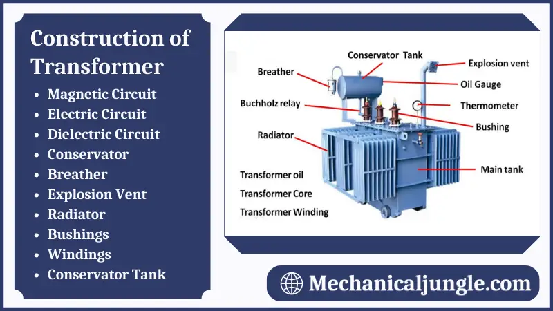
Construction of Transformer:
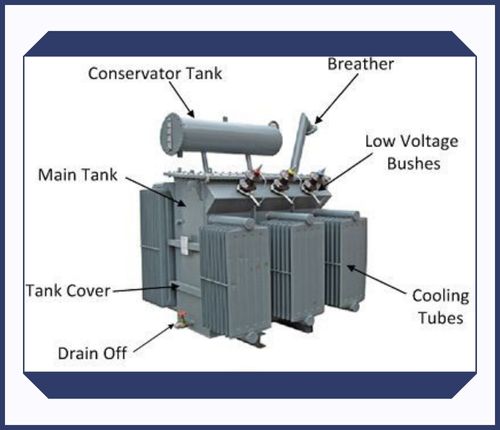
Basically, transformers consist of two inductive windings & laminated steels cores. The coil is insulated from each other as wells as from the steels cores. A transformer may also include a container for winding, and core assembly called a tank, suitable bushings for taking our terminals, and oil protectors to provide oil to the transformer tank for cooling purposes, etc.
The figure on the left shows the basics construction of a transformer. In all types of transformers, the core is constructed by stacking laminated sheets of steel with minimal air gaps between them to obtain a continuous magnetic path. The steel used has a high silicon content and is sometimes heat-treated to provide high permeability and low hysteresis loss.
A laminated sheet of steel is used to reduce the eddy current loss. Sheets are cut in the shape of E, I, and L. In order to avoid high reluctance in the joints, the edges of the joint are stacked with alternating laminations. That is, if the joints of the first sheet assembly area are placed on the front face, then the joints of the following assembly area are placed on the back face.
The construction of the transformer is of an iron core laminated with steel bands. Core lamination is constructed from insulated metals thin metal strips. These laminations are separated & wound around the limb using sheets of coats or parchment.
There are two types of winding, main and secondary winding. These windings are isolated from each other and are formed by an electric coil. The key feature of the core is to facilitate the winding of the magnetic flux and provide a low thrift direction with useful flux.
Also, Read: What Are Resistors? | Resistance with a Sinusoidal Supply | What Is Impedance? | Resistance VS Impedance
The construction of transformer parts are as follows:
#1. Magnetic Circuit
Magnetics circuits of transformers consist of a core and a yoke. The direction of magnetic flux flow is given by the circuit. A laminated steel core and two coils make up the transformer. The two coils are shielded from each other and also from the core. The cores of the transformer are made of a steel sheet or piece of silicon steel assembled to provide a continuous magnetic path. Silicon steel materials have minimal hysteresis losses at normal flux densities. The vertical position in which the coils are wound is called the limb, while the yoke is known as the horizontal position.
#2. Electric Circuit
Transformer electrical circuit consists of main & secondary copper windings. Rectangular cross-section conductors are commonly used for low-voltage windings as well as high-voltage windings for large transformers. A circular cross-section conductor is used for the high-voltage winding in a small transformer. Depending on the main structure & how the main and secondary windings are placed around it, transformers are known as core type and shell type.
In the manufacture of a transformer, the core of the transformer is usually made with a high permeability material, such as silicon steel lamination. A transformer core can be made in two ways, depending on the configuration of the main and secondary windings. Those are the two approaches:
- Core Type Fabrication
- Shell Type Construction
2.1. Core Type Construction
In the basic core style of transformer manufacturing, a rectangular lamination of the frame is made to shape the core of the transformer. Laminate is cut as L-shaped strips.
To prevent high resistance of joints where the laminates are bolted against each other, alternating layers are arranged to remove continuous joints. The main & secondary windings are interleaved to reduce the leakage current.
One-half of the winding is wound around each part of this type of core and is enclosed in such a way that no magnetic flux loss can occur and flow leakage is minimized.
This form of a structure appears to be very helpful for the diffusion of flow, with the windings covering each organ and thus the flow circulating throughout the heart.
2.2. Shell-Type Construction
The next part in the construction of a transformer is the individual pieces of shell-type transformers that are cut into the shapes of longs E and I strip.
It has two magnetic circuits, & its heart consists of three organs. The central limb carries the entire flow, while the lateral organs carry half the flow.
The diameter of the middle is also twice the diameter of the external organs. The winding rotates around the interior of the main ring in a shell-style structure of the core to form a shell on the outside of the core winding.
Since all windings are wound around the same middle arm, this arrangement also eliminates leakage of current.
#3. Dielectric Circuit
Dielectric circuits have insulations that are used on transformers to insulate major components in various positions. The center is laminated to reduce the eddy current loss. Laminations are insulated from each other by lights covers of varnishes or an oxide layer. The thickness of laminates ranges from 0.35 mm to 0.5 mm at a frequency of 50 Hz.
That’s not the end! Along with the transformer’s build, you can also find a winding and core assembly container called a “tank,” bushings for taking up terminals, an oil protector to supply oil to the transformer tank for cooling purposes, etc.
#4. Conservator
Cylindrical tanks on the top or roof of the transformer’s main tank are used for the preservative. A wide cover is provided which can be opened from time to time for proper servicing and cleaning of the transformer. This insulating oil acts as a buffer for the transformers.
When the transformer is fully charged & the transformer temperature is high, there is an increase in the amount of air inside the transformer. If the oil level rises & falls at the same time, the conservator provides enough room inside the transformer for this increased oil.
#5. Breather
Air acts as a heart in the construction of a transformer. As the transformer temperature rises, the insulating oil in the transformer heats up. When the oil heats up & expands, the transformer breathes air, and the oil cools, and the oil level drops.
The oils levels in the chamber rise & falls as the breather brings air in and out to cool the oil. This air contains moisture, which contaminates the oil and thus spoils the consistency of the oils. Breathers are packed with silica gel to remove this moisture.
The main purpose of silica gel is to separate the moisture from the oil while maintaining the consistency of the insulating oil. The color of silica gel turns pink due to the absorption of moisture from the oil.
#6. Explosion Vent
It is important for the transformer to be constructed to be safe and to avoid damage; Therefore, there is an explosion vent, a thin aluminum pipe fitted at both ends of the transformer.
As the temperature in the transformer rises rapidly and additional pressure is generated, the explosive vent helps to relieve the pressure.
#7. Radiator
Cooling of oil in a transformer is the major feature of a radiator. The radiators are detachable tubes, the upper & lower parts of which are connected by a valve to the transformer tank. When the transformer washing and repair work is complete, the valve prevents oil from draining when the radiator is removed from the transformer.
Transformer oil is heated and flows up into the main tank while the transformer is in operating order & reaches the radiator through the upper valve. It cools down there, and the oil flows through the lower valve of the irradiation unit again into the transformer tank, & these mechanisms continue.
#8. Bushings
Bushings are an insulating system in the construction of a transformer that enables an electrical conductor to move electrical energy safely through it.
When a significant amount of electrical energy travels through it, it provides the electric field strength to counteract the insulation of the conductors. Small transformers use solid porcelain-type bushings, and large transformers use oil-filled condenser-type bushings.
The most commons cause of bushing failure is the moisture inlet damaging the transformer. The power factors of the bushing will still be at a steady state, so if a power factor difference is observed, the insulation will wear out. The acceptance or routine test and the measure is known as the double power factor test would define this.
#9. Windings
The winding arrangement is also an important concern in the manufacture of transformers. The winding of a transformer is made of a conducting material to allow magnetic flux to build up, and then-current can be transferred from one winding to another.
To increase the magnetic flux, these windings are wound on two separate iron parts, as iron is an important conductor & exhibits excellent magnetic properties. They are often insulting each other by this coil.
Since these two coils are wound on two separate limbs, flux leakage often occurs because of the distance between them; the magnetic flux density decreases, and consequently, the magnetic coupling between the two coil windings decreases.
#10. Conservator Tank
Since it is often important for a type of container to keep the transformer core and windings tight, a tank is used to preserve the laminating fluid, reduce its oxidation, and maintain oil levels.
The tank also includes a number of other important systems, such as a set of adequate sensors and a relay sensing gas, which acts as a gas sensor and alerts if the presence of some unwanted gas is sensed and external. The circuitry is automatically protected by disconnecting the transformer.
Conclusion:
It’s all about building the transformer. In the post, we shed some light on the definition of the transformer, its parts, and how it is made. If you’re interested in finds out more about building transformers, register on Linkquip and let us know in the comments section. Please share this post with other friends.
Types of Transformers based on Cooling Method:
#1. Oil Filled Self-Cooled Type
The oil-filled self-cooling type uses small and medium-sized distributions transformers. The assembled winding & core of such transformers are mounted in a welded, oil-tight steel tank provided with a steel cover.
As the core is put back in its proper place, the tank is filled with pure, high-quality insulating oil. The oil helps to transfer heat from the core and winding to the matter from where it is radiated to the surroundings.
For small-sized transformers, the tanks are usually on a smooth surface, but larger-sized transformers require a greater heat radiation area, and that too without disturbing the cubical capacity of the tank. This is achieved by re-melting the cases. Stills, larger sizes are provided with radiations or pipes.
#2. Oil Filled Water Cooled Type
This type is used for the more economical construction of large transformers, as the self-cooling method mentioned above is very expensive. The same method is used here – the winding and the core are immersed in oil.
The only differences are that there is a cooling coil located near the surface of the oil, through which the cooling water circulates. This water carries heat from the device. This design is usually applied to transformers that are used in high voltages transmission lines.
The biggest advantages of such designs are that such a transformer does not require housing other than its own. This brings down the cost to a great extent. Another advantage is that this type of maintenance and inspection is needed only once or twice a year.
#3. Air Blast Type
These types are used for transformers that use voltages below 25,000 volts. The transformers are housed in a thin sheet metal box that is open at both ends through which air flows from bottom to top.
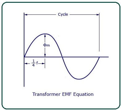
E.M.F Equation of a Transformer:
Let,
- NA = number of turns in the primary
- NB = number of turns in secondary
- Ømax = Maximums fluxs in the core in webers = Bmax X A
- f = Frequency of alternating currents input in hertz (HZ)
As shown in the figure above, the core flux increases from its zero value to maximum value Ømax in one-quarter of the cycles, that is in ¼ frequency second.
Therefore, averages rates of change of fluxes = Ømax/ ¼ f = 4f ØmaxWb/s Now, the rates of changes of flux per turn mean induced electromotive force in volts. Therefore, averages electro-motive forces induced/turn = 4f Ømaxvolt If flux Ø varies sinusoidally, then the r.m.s value of induced e.m.f is obtained by multiplying the average values with the form factor.
Form Factor = r.m.s. value/averages value = 1.11
Therefore, r.m.s values of e.m.f/turn = 1.11 X 4f Ømax = 4.44f Ømax
Now, r.m.s values of induced e.m.f in the wholes of primary winding
= (induced e.m.f./turn) X Numbers of primarys turn
Therefores,
E¬A = 4.44f NAØmax = 4.44fNABmA
Similarly, r.m.s values of induced e.m.f in secondary are
E¬B = 4.44f NB Ømax = 4.44fNBBmA
In an ideals transformers on no load,
VA = EA & VB = EB , where VB is the Terminals voltages
Voltage Transformations Ratio (K)From the above equations, we get
EB/ EA = VB/ VA = NB/NA = K
This constant K is known as the voltage transformations ratio.
(1) If NB>NA, that is K>1, then the transformer is called a step-up transformer.
(2) If NB<1, that is K<1, then the transformer is known as a step-down transformer.
Again for an ideal transformer,
Input VA = Output VA
VAIA = VBIB
or, IB/IA = VA/VB = 1/K
Hence, a current is in inverse ratios of the voltages transformation ratio.
Applications of Transformer:
Transformers are used in most electronic circuits. A transformer has only three applications;
- To increase the voltage and current.
- To reduce voltage and current.
- To stop DC – Transformers can only pass alternating current so that they can completely prevent DC from passing to the next circuits.
Also, Read: Scotch Yoke Mechanism | Working Principle of Scotch Yoke Mechanism | Construction of Scotch Yoke Mechanism
Frequently Asked Questions (FAQ)
Transformer Rectifier
A Transformer Rectifier Unit (TRU) combines the functions of a Transformer and a Rectifier into one unit. In aircraft applications, the TRU converts the 120V AC power generated by the engine or APU generators or provided by a Ground Power Unit (GPU) to 28V DC power for use by various electrical components.
Instrument Transformer
Instrument transformers are high-precision electrical devices used to isolate or transform voltage or current levels. The most common application of instrument transformers is to power equipment or measure high voltage or high current circuits, safely isolating secondary control circuits from high voltage or current.
Distribution Transformer
A distribution transformer, or service transformer, is a transformer that performs the final voltage transformation of the electrical distribution system, lowering the voltage used in the distribution lines to the level used by the customer.
Transformer
A transformer is a passive component that transfers electrical energy from one electrical circuit to another circuit or multiple circuits.
Types of Transformer
- Power Transformers.
- Autotransformers.
- Generator Step-Up Transformers.
- Auxiliary Transformers.
Construction of Transformer
- Magnetic Circuit
- Electric Circuit
- Dielectric Circuit
- Conservator
- Breather
- Explosion Vent
- Radiator
- Bushings
- Windings
- Conservator Tank
Basic Principle of Transformer
The basic principle behind the working of a transformer is the phenomenon of mutual induction between two windings linked by common magnetic flux. The figure at right shows the simplest form of a transformer. Basically, a transformer consists of two inductive coils; primary winding and secondary winding.
Like this post? Share it with your friends!
Suggested Read –
- Bolt Head Types
- Auxiliary Boilers
- What Is a Comparator | Types of Comparators
- Lancashire Boiler | Lancashire Boiler Diagram | Steam Boiler Working Principle | Steam Boiler Parts And Function
- What Is Forming | Types of Forming | Forming Process in Manufacturing | Metal Forming Processes | Forming Operations
- What Is Boiler? | Types of Boiler | Steam Boiler | How Boiler Work | Boiler Operation | Boilers Diagram | How Does a Steam Boiler Work
- What Is Sigma Comparator | Construction of Sigma Comparator | Applications of Sigma Comparator | Advantages of Sigma Comparator | Disadvantages of Sigma Comparator