Important Point
What Is Hydraulic Braking System?
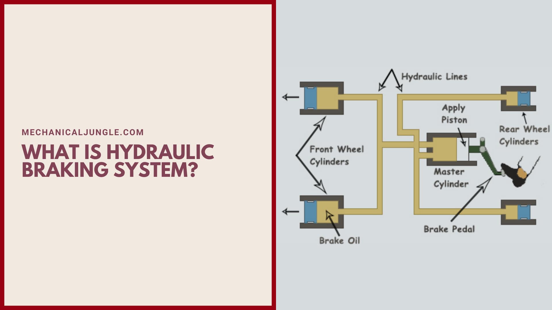
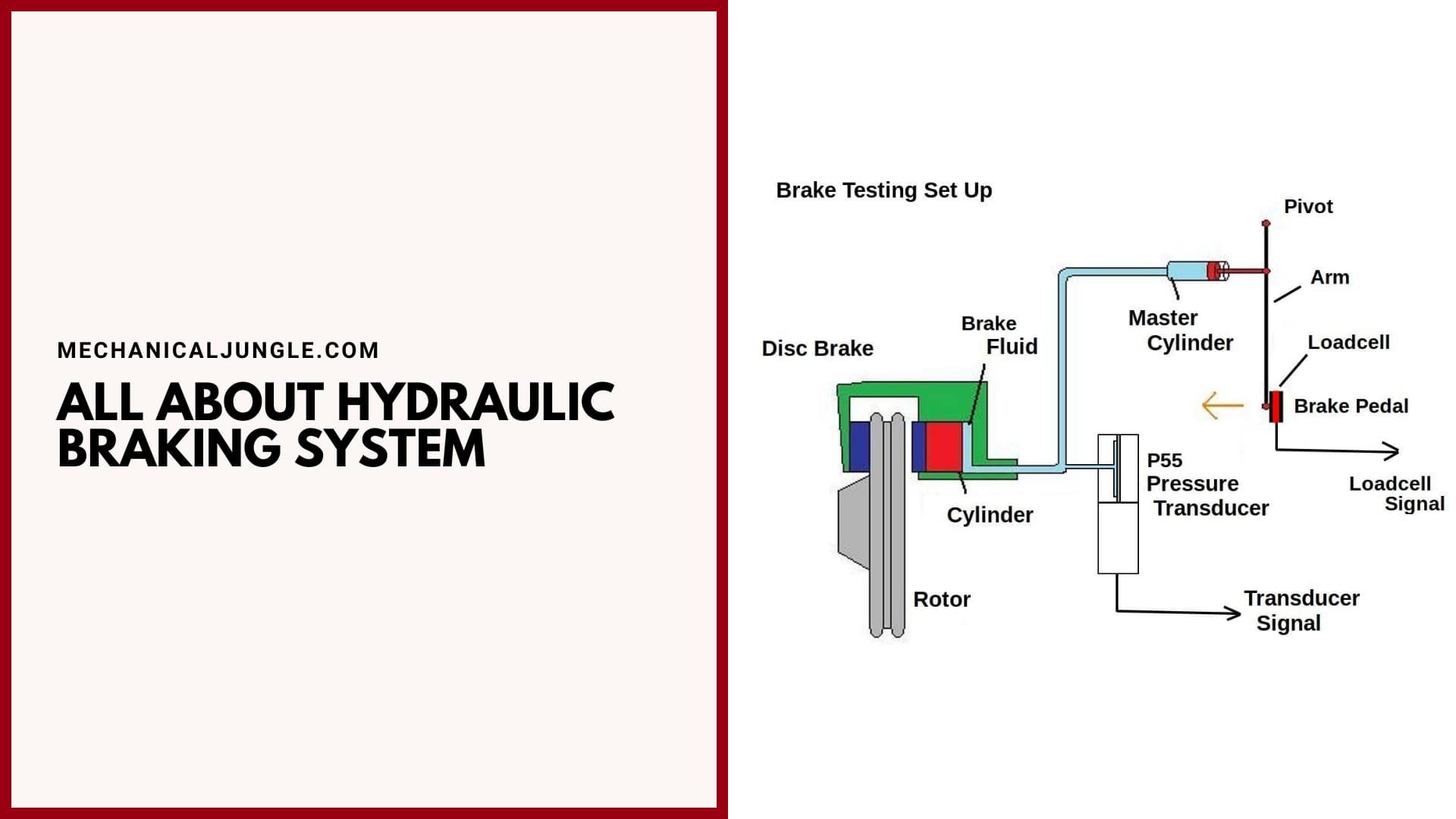
A hydraulic brakes system is a braking mechanism that uses brake fluid to transmit force into the system. The fluid transfers pressure from the control mechanism to the braking mechanism. Hydraulic braking systems are widely used in low-speed four-wheelers such as the Tata Ace. It works with the drum type, while the disc type is used in almost all cars.
It is also used on some bikes. Single-acting hydraulic sacks are used in some Pulsar front-wheel brakes, while dual-acting hydraulic brakes are used in almost all situations described above.
In thises type of braking system, the mechanical forces transmitted by the driver on the brake pedal are converted to hydraulic pressure by a device known as a master cylinder (see article on the master cylinder), and then this hydraulic pressure is sent to the final drum or disc. It goes to stop or accelerate the caliper vehicle.
The hydraulic brakes are a type of braking system widely used in automobiles with the application of hydraulic fluid. The working principle of hydraulic braking systems is based entirely on Pascal’s law, which states that the intensity of pressure inside a system closed by a liquid is always the same in all directions.
A good and efficient braking system is an essential part of a system running like automobiles & machines. Generally, in automobiles, different types of braking system are used as per the requirement as each type of braking system has its own applications and advantages.
Construction of Hydraulic Braking System:
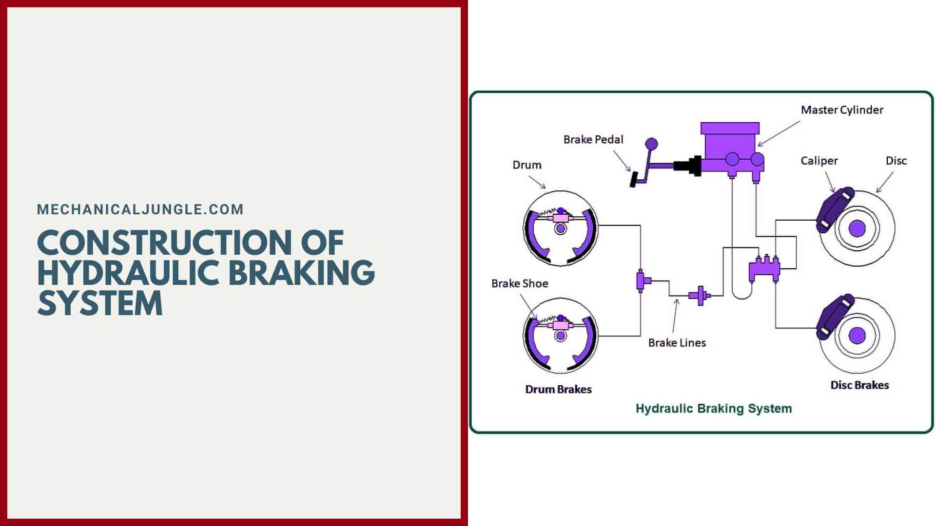
The construction of hydraulic braking systems involves the following part arrangement. Brake pedal or level, a wreath, also known as an actuating rod, a master cylinder assembly is carrying a piston assembly. It is composed of one or two pistons, a return spring, a series of gasket or O rings, and a fluid reservoir.
The construction of hydraulic braking systems consists of reinforced hydraulic lines, & the brake caliper assembly consists of one or two hollows aluminum or chrome-plated steels piston. This is known as the caliper piston.
A thermally conductive brake is a set of pads and rotors, also known as a brake disc or drum attached to an axle. A glycol-ether-based brake fluid filled the system to force the four wheels. However, other liquids may also be employed. Suddenly, manufacturers start designing passenger vehicles with drum brakes on four wheels.
Traditionally, disc brakes are used in the front wheel, while drum brakes are employed for the rear wheel. Disc brakes have better heat dissipation & greater resistance to fading and are safer than drum brakes. This is why four-wheel disc brakes have increased significantly over the year. In addition, hydraulic brake pedals provide faster and more consistent pad return upon release.
Also, Read: What Is Marine Boiler? | Principle of Marine Boiler | Types of Marine Boiler
Parts of Hydraulic Braking System:
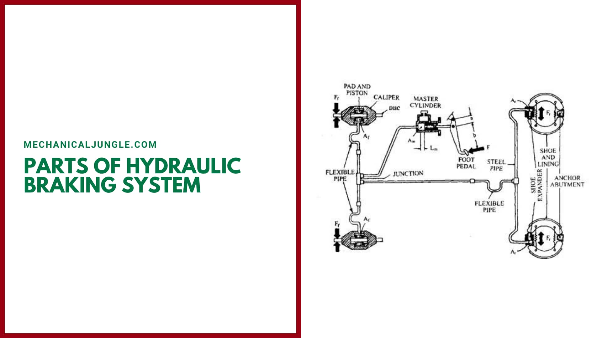
#1. Master Cylinder
It is the main part of the entire assembly. It acts as a hydraulic actuator with a piston-cylinder arrangement. It is responsible for converting mechanical force into hydraulic force.
Fluid is compressed and pressurized into the master cylinder as a brake pedal that is transmitted to the brake assembly via hydraulic lines.
#2. Brake Pedal and Mechanical Linkage
The brake pedal acts as the input of the master cylinder, or we can say that the entire assembly will start working when the brake pedal is pressed. It is manually pressed when we have to stop or slow down the running body.
It is connected with a small mechanical contact such as a spring that helps retract the pedal and further connects to the master cylinder. After the execution of the brake pedal, the master cylinder comes in handy.
#3. Hydraulic/Brake Fluid Reservoir
It is like a small tank for braking fluid. It is directly connected to the master cylinder for proper handling of hydraulic braking. It is necessary to maintain the exact amount of braking fluid throughout the assembly.
Sometimes due to small leaks, the fluid level goes down into the master cylinder, so a reservoir is needed to maintain the proper amount of brake fluid in the working operation. Braking fluid moves from the reservoir to the master cylinder when needed.
#4. Hydraulic Lines
Hydraulic lines are the relationships between the various components of a braking system. Braking fluid passes through these lines from the master cylinder to the brake.
These are small diameter pipes that replace various types of mechanical linkage in the case of mechanical brakes.
#5. Brake Calipers
In the case of brake brakes, brake calipers are parts of the braking system that performs the brakes. Inside the brake calipers, pistons are placed, which are responsible for braking. Brake pads are also attached to pistons.
Calipers are placed on the circumference of the disc. The disc brake is an externally applied braking system. A disc is placed between the calipers.
#6. Drum Cylinder
A drum cylinder is a type of small cylinder that is used in drum brakes, and the brake is located inside the drum and is connected to both brake shoes. The drum brake is an internally applied brake.
Working of Hydraulic Braking System:
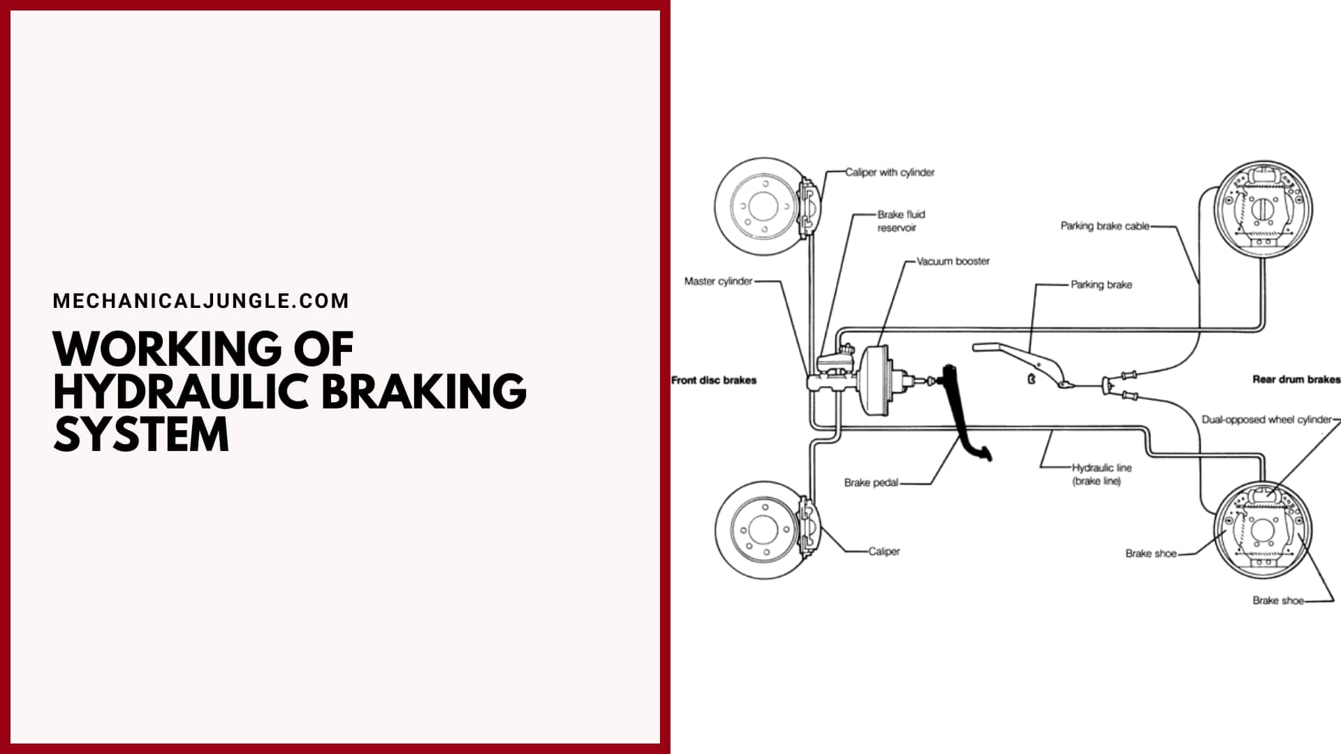
The work of the hydraulic braking system is very simple. To execute the brakes, we have two types of components: a disc brake and a drum brake.
The initial work is the same for both types, but the execution technique is different. Disc brakes are externally applied brakes through the brake calipers and discs, while drum brakes are applied internally through brake shoes and brake drums.
The working of both the types is as follows:-
#1. Drum Hydraulic Brake
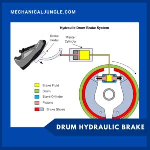
The following process occurs when the driver applies a brake in a vehicle equipped with hydraulic brakes mounted on the drum. The speed or activation of the brake pedal causes a master cylinder to move a rod connected between the pedal and the piston, which in turn pushes the piston of the master cylinder inside the master cylinder like a medical syringe.
This movement of the pistons inside the master cylinders causes compression of the brake fluid inside the master cylinder, which in turn converts mechanical energy to hydraulic pressure. Thises highly compressed brake fluid from the master cylinders moves inside the brake, and this hydraulic pressure transfers from the master cylinder to the brake drum.
When this high-pressure brake fluid o enters the wheel cylinder or drum cylinder due to its high pressure, there is movement in the cylinder piston, which in turn expands the static brake shoe attached to it.
Due to the expansion of the brake shoe, a friction contact is formed between the brake shoes and the drum lining (rotating drum part), which in turn converts the kinetic energy of the vehicle into heat energy & finally braking.
Single-acting drum-type braking – Single-acting drum type hydraulic brakes work exactly as stated above; this type of braking provides braking force in the single wheel or single pair.
Double Acting Drum Type Braking – High-pressure brake fluid from the master cylinder in double-acting hydraulic brakes is divided into two directions, i.e., all wheels of bikes and all wheels of cars, due to the use of tandems master cylinders (article on master cylinder).
#2. Disc Hydraulic Brakes
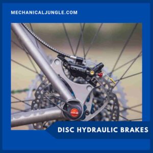
The process involved is similar to that of a drum drum when the driver brakes a vehicle equipped with a disc-type hydraulic brake when the high-pressure brake fluid enters the brake lines but is slightly different thereafter – High-pressure brake fluid from the brake lines enters the disc caliper cylinder of the disc brake system.
This high-pressure brake fluid causes motion in the piston of the caliper cylinder, which in turn causes the speed of the brake pads attached to the piston inside the caliper.
Due to this movement of the brake pads, there is the clamping of the rotating disc rotor, and due to this frictionless contact between the brake pads and the rotating disc rotor, the kinetic energy of the vehicles are converted into heat energy, which in turn would be stopped, or de is. Accelerate the vehicle.
Single Acting Disc Type Braking – The function of single-acting disc type hydraulic braking is exactly the same as mentioned above; this type of braking provides a single braking force in the single wheel or single pair wheels.
Double-acting disc type braking – In a double-acting disc type hydraulic brake, high-pressure brake fluid is delivered in 2 directions from the master cylinder, that is, due to the use of tandem master cylinders in both wheels and bikes in all wheels.
Application of Hydraulic Braking System:
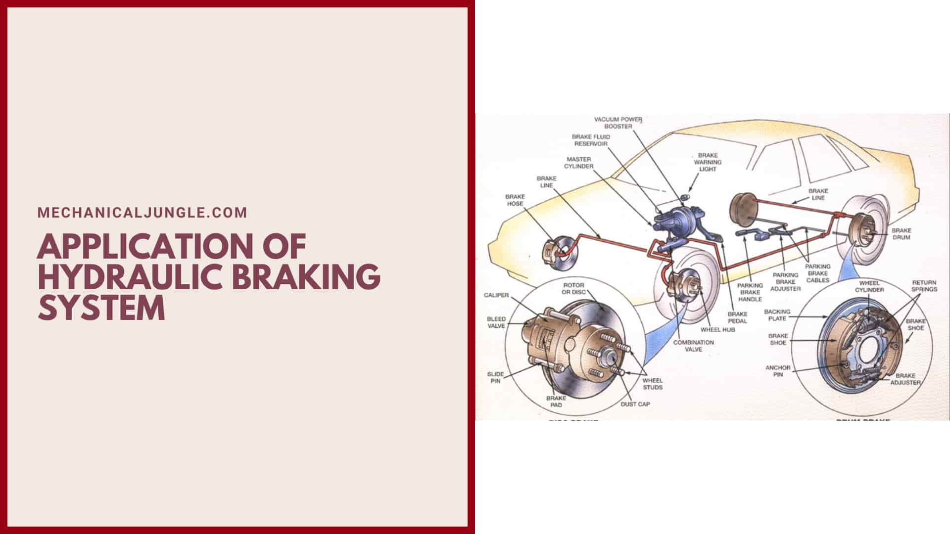
- Drum type hydraulic brakes – They are used in some low-speed four-wheel vehicles such as Tata Ace.
- Disc Type Hydraulic Brakes – They are used in almost all cars like Maruti Suzuki Swift, Hyundai i20, etc., & also in bikes like Bajaj Pulsar 180, KTM Duke 390, etc.
- Single-acting hydraulic brake – Pulsar 180 front brakes are of single-acting type.
- Dual Acting Hydraulic Brakes – All of the above cars.
Frequently Asked Questions (FAQ)
Hydraulic Brake System
The hydraulic braking system is a type of braking system in which, unlike the mechanical braking system, hydraulic fluid is used to transmit the brake pedal or brake lever force from the brake pedal or brake lever to the final drum shoes or disc caliper in order to achieve braking.
Hydraulic Brakes Parts
The following are the main parts of your vehicle’s hydraulic brake system. Brake Pedal. The pedal is what you push with your foot to activate the brakes.
- Brake Master Cylinder.
- Brake Lines.
- Rotors/Drums.
- Wheel Cylinders.
- Brake Pads.
Brake System Components
Brake system components are brake pedal, brake booster, master cylinder pipes, slave cylinders, brake pistons, pads, and rotors. This refers to cars that have disc brakes.
Components of Brake System
The major brake system components include the brake pedal, brake booster, brake master cylinder, brake lines and hoses, brake calipers and pistons, disc brake pads or brake shoes, disc brake rotors or brake drums, brake fluid, anti-lock brake system (ABS) control module, wheel speed sensors, and there are many more individual parts within the above component groups.
Hydraulic Brake Parts
Hydraulic brake parts:
- Brake Calipers
- Brake Hardware
- Brake Pads & Shoes
- Brake Rotors
- Hydraulic Brake Valves & Switches
- Master Cylinders
Hydraulic Braking System Components and Operation
A hydraulic brake circuit has fluid-filled master and slave cylinders connected by pipes. The master cylinder transmits hydraulic pressure to the slave cylinder when the pedal is pressed. When you push the brake pedal it depresses a piston in the master cylinder , forcing fluid along the pipe.
Advantages of Hydraulic Braking System in Vehicles
Hydraulic disk brakes also provide more braking power because they have a greater contact area, which supports heat dissipation. They also rarely fail, making them reliable at high speeds and work better compared to mechanical brakes in wet and muddy conditions.
Hydraulic Braking System Maintenance and Troubleshooting
Maintaining and troubleshooting a hydraulic braking system is crucial for ensuring the safety and proper functioning of your vehicle’s brakes. Here are some maintenance tips and troubleshooting steps for a hydraulic braking system:
Maintenance Tips:
- Regular Inspections: Periodically inspect the brake lines, hoses, and connections for any signs of damage, leaks, or corrosion. Replace any worn-out or damaged components promptly.
- Brake Fluid Replacement: Follow the manufacturer’s recommendations for brake fluid replacement intervals. Over time, brake fluid can absorb moisture, which can reduce its effectiveness. Flushing and replacing the brake fluid helps maintain optimal braking performance.
- Bleeding the Brakes: Air bubbles in the hydraulic system can lead to a spongy brake pedal and reduced braking efficiency. Bleeding the brakes removes air from the system. Consult your vehicle’s manual or seek professional help to perform this procedure correctly.
Troubleshooting Steps:
- Soft or Spongy Brake Pedal: If the brake pedal feels soft or spongy, it may indicate air in the hydraulic system. Bleeding the brakes can help remove the air. If the problem persists, there may be a leak in the system that needs to be identified and repaired.
- Brake Fluid Leaks: Check for any visible brake fluid leaks around the brake lines, hoses, calipers, or wheel cylinders. Leaks can lead to a loss of brake pressure and require immediate attention. Replace or repair the affected components as necessary.
- Brake Noise: Squealing, grinding, or other unusual noises during braking may indicate worn-out brake pads or rotors. Inspect the brake pads and rotors for excessive wear and replace them if necessary. Proper lubrication of brake caliper slide pins and pad contact points can also help reduce noise.
Hydraulic Braking System Manufacturers in the USA
- Catalog. Applied Power Solutions.
- Motion Industries, Inc.
- Force Control Industries, Inc.
- The Rowland Company.
- Tolomatic, Inc.
Upgrade Options for Hydraulic Braking System Performance
Performance brake systems often include upgraded components such as high-performance brake pads, slotted or drilled brake rotors, stainless steel braided brake lines, and larger calipers to improve stopping power and heat dissipation.
Hydraulic Brake Diagram
I’m sorry, but as a text-based AI model, I cannot provide visual diagrams. However, I can describe the basic components of a hydraulic brake system:
- Brake Pedal: The brake pedal is located inside the vehicle and is pressed by the driver’s foot to activate the brakes.
- Brake Booster: The brake booster assists in applying force to the brake pedal. It uses vacuum or hydraulic pressure to amplify the force applied by the driver.
- Master Cylinder: The master cylinder is connected to the brake pedal and generates hydraulic pressure. When the brake pedal is pressed, it pushes a piston inside the master cylinder, forcing brake fluid into the brake lines.
- Brake Lines: Brake lines are metal or flexible rubber hoses that carry the brake fluid from the master cylinder to the wheels. They are typically made of steel or a combination of rubber and steel.
- Brake Calipers: Brake calipers are located at each wheel and contain pistons that squeeze the brake pads against the brake rotors when the brakes are applied. The calipers are connected to the brake lines and receive hydraulic pressure from the master cylinder.
Hydraulic Brake Is Based on
Hydraulic brakes are based on Pascal’s law. Pascal’s law states that when a fluid is kept in a closed container, the pressure at one point will be equal to every other point on the fluid. We know that pressure is force per unit area.
Working of Hydraulic Brakes
When the brake is pressed by applying a force F1 the pressure in the braking fluid is increased. This is transmitted to the pistons with larger area which press against the break shoes (F2) and the friction between the shoes and the rotor causes a braking torque to be generated, slowing the vehicle.
Hydraulic Brake System Components
- Brake Pedal/Brake Lever. The brake pedal or brake lever is also known as an input device as it is used to determine when the brakes will be activated and deactivated.
- Master Cylinder.
- Reservoir Tank.
- Hydraulic Pipe.
- Caliper / Brake Actuator.
Types of Hydraulic Brakes
- Band—Band brakes are the simplest type of brake.
- Drum—Drum brakes press shoes against a spinning surface.
- Disc—Disc brakes have brake pads, a caliper, and a rotor.
- Cone—Cone brakes consist of a cup and a cone that is lined with a heat- and wear-resistant friction material.
Hydraulic Brake Principle
Hydraulic brakes work on the principle of Pascal’s law. According to this law whenever pressure is applied on fluid it travels uniformly in all the directions.
Hydraulic Brake System Working
A hydraulic brake circuit has fluid-filled master and slave cylinders connected by pipes. The master cylinder transmits hydraulic pressure to the slave cylinder when the pedal is pressed. When you push the brake pedal it depresses a piston in the master cylinder , forcing fluid along the pipe.
How Do Hydraulics Work?
Like this post? Share it with your friends!
Suggested Read –
- Air Brake System
- Parts of a Disc Brake
- Hydraulic Brake System
- How Drum Brakes Work
- Electrochemical Deburring
- Domestic Electrolux Refrigerator | Different Components of Domestic Electrolux Refrigerator
- Types of Angle Plates | Box Angle Plate of Angle Plate | Swivel Angle Plates of Angle Plate | Cast Iron T-Slotted Angle Plate of Angle Plate
- What Is Wilson-Hartnell Governor? | Wilson Hartnell Governor | Construction of Wilson Hartnell Governor | Working of Wilson Hartnell Governor
- Cochran Boiler | Cochran Boiler Working | Working Principle of Cochran Boiler | Applications of Cochran Boiler | Advantages & Disadvantages of Cochran Boiler
- What Is Cupola Furnace? | Cupola Furnace Design । Cupola Construction | Purpose of Cupola | Working Principle of Cupola Furnace: | Advantages of Cupola Furnace | Disadvantages of Cupola Furnace | Applications of Cupola Furnace