Important Point
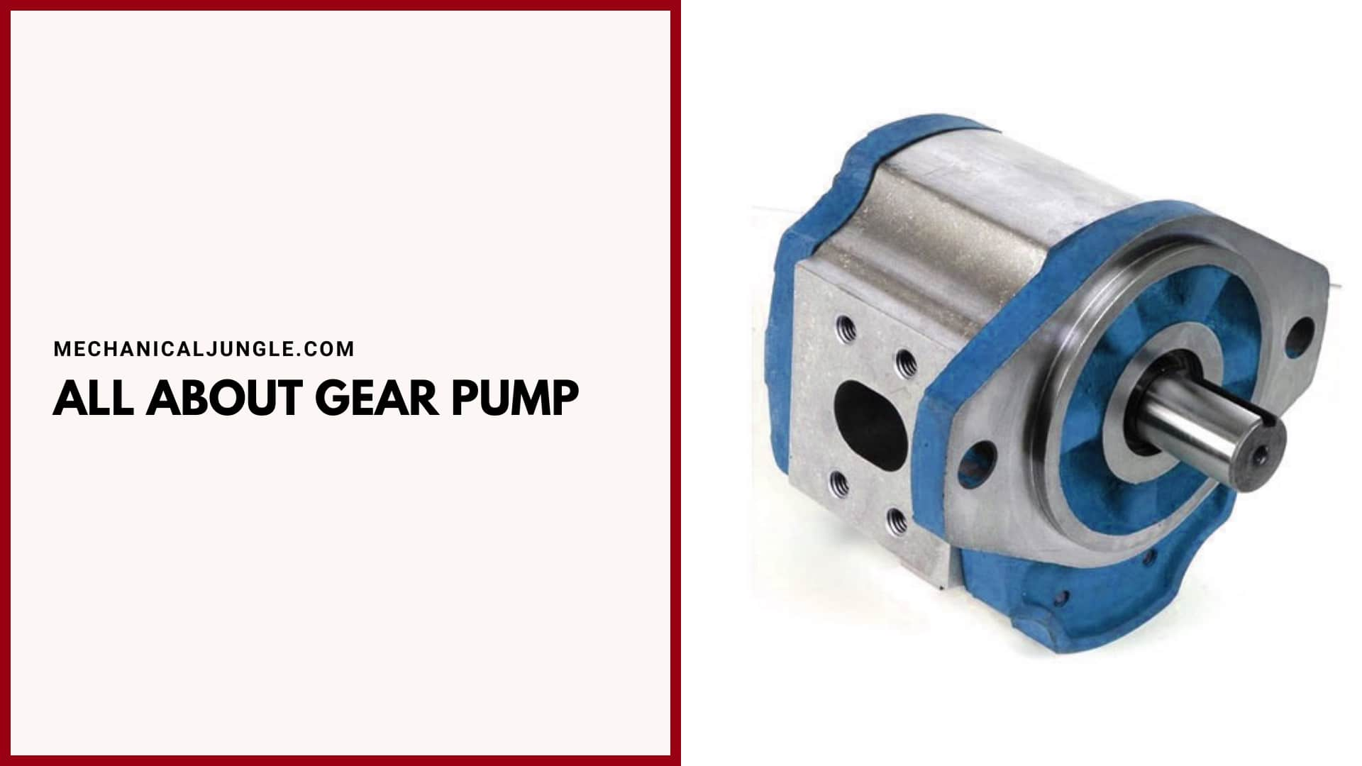
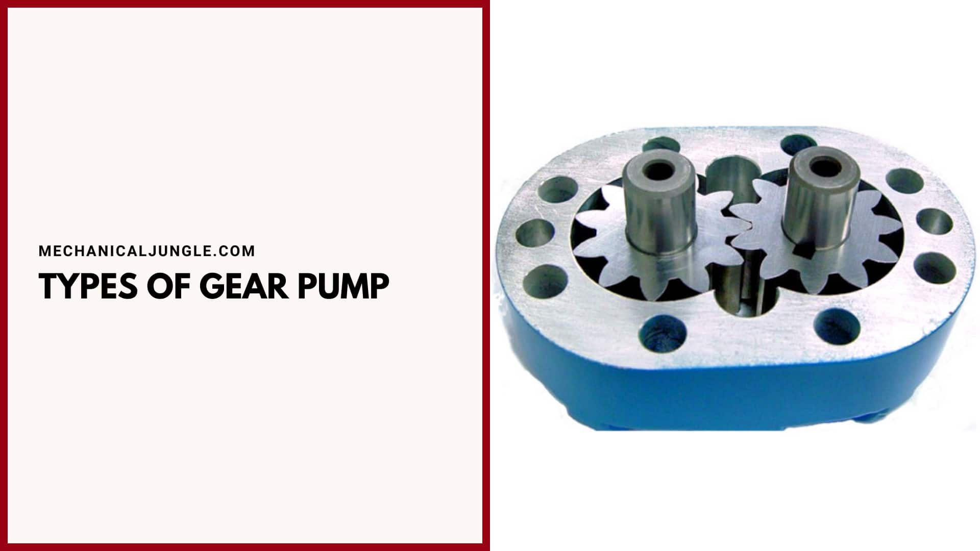
What Is a Gear Pump?
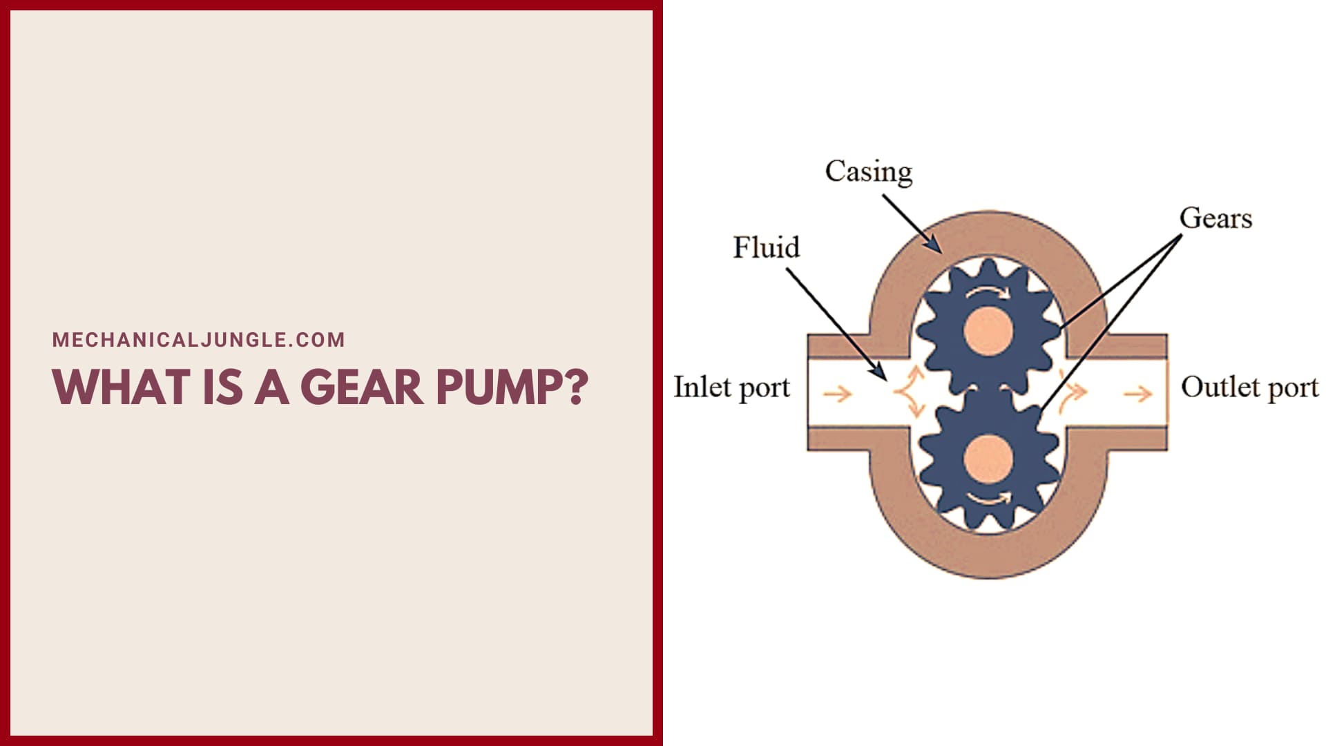
A gear pump category belongs to the positive displacement pump, consisting of a continuous delivery rotary pump. With the help of gear meshings, mechanical energy is converted into fluid energy, and this creates zero suction.
The space that is in the middle of the gear meshing, which carries a high level of viscous fluids towards the surface of the wall and then to the output. This pump works effectively for extended levels of viscous liquid such as oil as it does not require any priming.
Also, Read: What Is Vane Pump? | Types of Vane Pumps | Working of Vane Pump | Components of Vane Pump
Gear Pump:
The gear pump is a type of positive displacement rotary pump. In a gear pump, a fluid moves a certain amount of fluid using an interlocking gear and then moving it with the gear rotating. These pumps deliver a pulse-free flow that is directly proportional to the rotational speed of the gear.
Gear pumps are mainly used to develop high pressure. The gear pump is a positives displacement pump & also a fixed displacement pump. A positive displacement pump means that this pump provides a constant flow at a certain speed regardless of the change in pressure, & a fixed displacement pump means that it rejects a certain amount of fluid per revolution of the shaft.
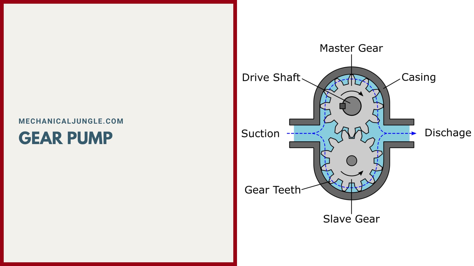
The gear pump was invented around 1600 by Johannes Kepler. In a gear pump, there are usually two gears. One gear is the driver gear or power gear, and the other is the gear or idle gear. The driver gear is connected to some key movers or to a mechanical power source.
Driver gear is also known as masters gear, and driven gear is also known as slave gear. The driver gear is rotated either using an electric motor or using an I.C. engine or using a hand.
Components of Gear Pumps:
#1. Driver Gear
The driver gear is connected to the prime mover. It rotates using power from the prime mover.
#2. Driven Gear or Idle Gear
The driven gear is forged with the drive gear, and the driver rotates the gear.
#3. Casing
Both the driver gear & the driven gear are packed inside the casing of the gear pumps.
#4. Inlet Section or Suction Side
This is the section in the gear pump through which fluid enters the gear pump. The low-pressure liquid enters the pump from the inlet section.
#5. Outlet Section or Discharge Side
This is the section in the gear pump through which pressurized fluid is transported to the required area. High-pressure liquid flows from the pump to the outlet section.
#6. Prime Mover
In gear pumps, prime movers are used to providing power to the shaft in which the driver gear is mounted. It can be an electrical motor or an I.C. engine, or it can be manual labor.
#7. Safety Valve or Release Valve
A safety valve or release valves are installed on the discharge side so that the pump can be protected from being damaged if additional pressure arises when it is released.
Types of Gear Pump:
Typically, There Are Five Types of Gear Pumps:
- External Gear Pump
- Internal Gear Pump
- Lobe Pump
- Ge-Rotor Pump (Generated Rotor Pump)
- Screw Pump
#1. External Gear Pump
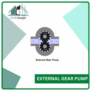
In an external gear pump, an external gear is used to pump fluid. In an external gear pump, two helical or spur gears are meshed with each other and placed inside the casing.
The gear used in this type of pump is external meshings types. In this type of pump, any gear type, either helical gear or spur gear, or any other type of gear, can be used. One of the two gears is the driving gear, and the other is the driven gear.
The driven gears will also rotate when the driver gear is rotated as both gear is in mesh with each other. In the external pump, partial vacuums are created at the inlet of the pump.
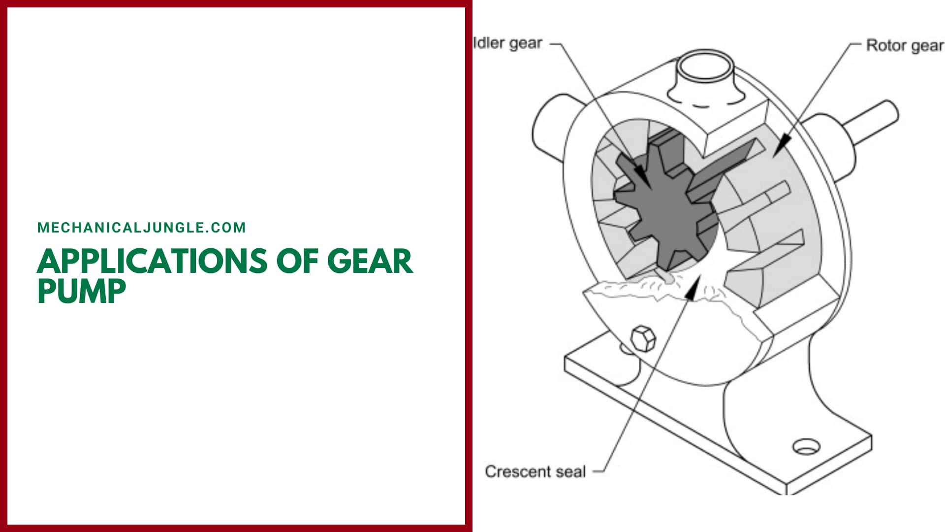
#2. Internal Gear Pump
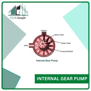
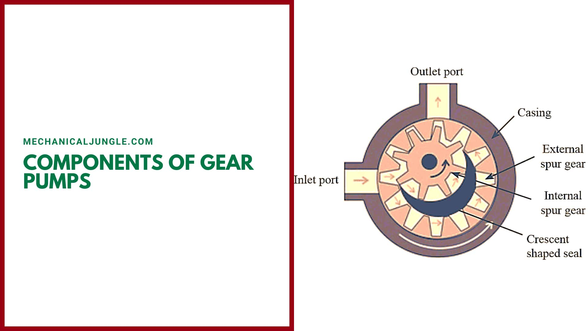
In an internal gear pump, the gear used to pump the fluid has an internal trap. In the internal gear pumps, the inner gear is smaller and has outer teeth, and the outer gear is the larger gear and has the inner teeth. Between the two gears of the internals gear pump, a crescent seal is provided that fills the gap between the two gears.
As the teeth in the inner gear mesh with the outer gear, a partial vacuum is created, causing the fluid to enter the gap between the crescent seal and the inner gear. After that, the fluid gets trapped between the inner gear and the crescent seal and travels from the inlets to the outlet of the internal gear pump.
#3. Lobe Pump
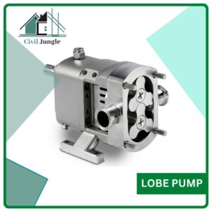
This is another type of external gear pump. In lobe pumps, vans are used in place of gear teeth. The number of lobes can be 3 or 4, depending on the requirements.
Two lobes are fitted inside the casings. The lobe is designed in such a way that the lobes almost hold each other instead of touching and rotating in the case of an external gear pump. Due to the large size of vans and the low number of vans, high discharge is achieved.
#4. Ge- Rotor (generated rotor) Pump
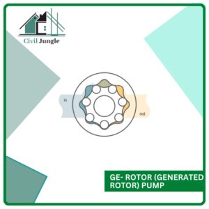
This pump has two generating rotors. One rotor has external teeth, & the other has internal teeth. The rotor with the outer teeth rotates inside the rotor with the inner teeth.
The number of teeth of the inner rotors is one less than that of the outer rotor. The shaft of the prime movers is coupled to the internal rotor. Therefore, the internal rotor is called the driver rotor.
Near the top of the Ge-Rotor pumps, the pocket size, i.e., the space between the outer and inner rotor, is negligible. Pocket size increases up to 180 degrees in the outer rotor teeth. So, the fluid is sucked near the inlets due to the vacuum between the inner rotor teeth and the outer rotor teeth.
After 180 degrees, when the fluid reached the bottom of the Ge-Rotor pump, the pocket-size begins to decrease, allowing the fluid to be transported through the outlet.
#5. Screw Pump
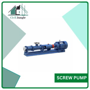
It is named screw pump because the screws are used in this pump to increase the pressure of the fluid. In this pump, the inlets are divided into two parts and have an outlet.
In screw pumps, one shaft has a left-hand screw, and the other shaft has a right-hand screw. Two inlets are present at the ends, & the outlet is in the opposite direction.
When the pumps are started, the liquid fills the gap between the threads of the screw at the edge of the inlet, and it moves axially along the screw from the inlet to the outlet due to the rotation of the liquid screw.
Working of Gear Pump:
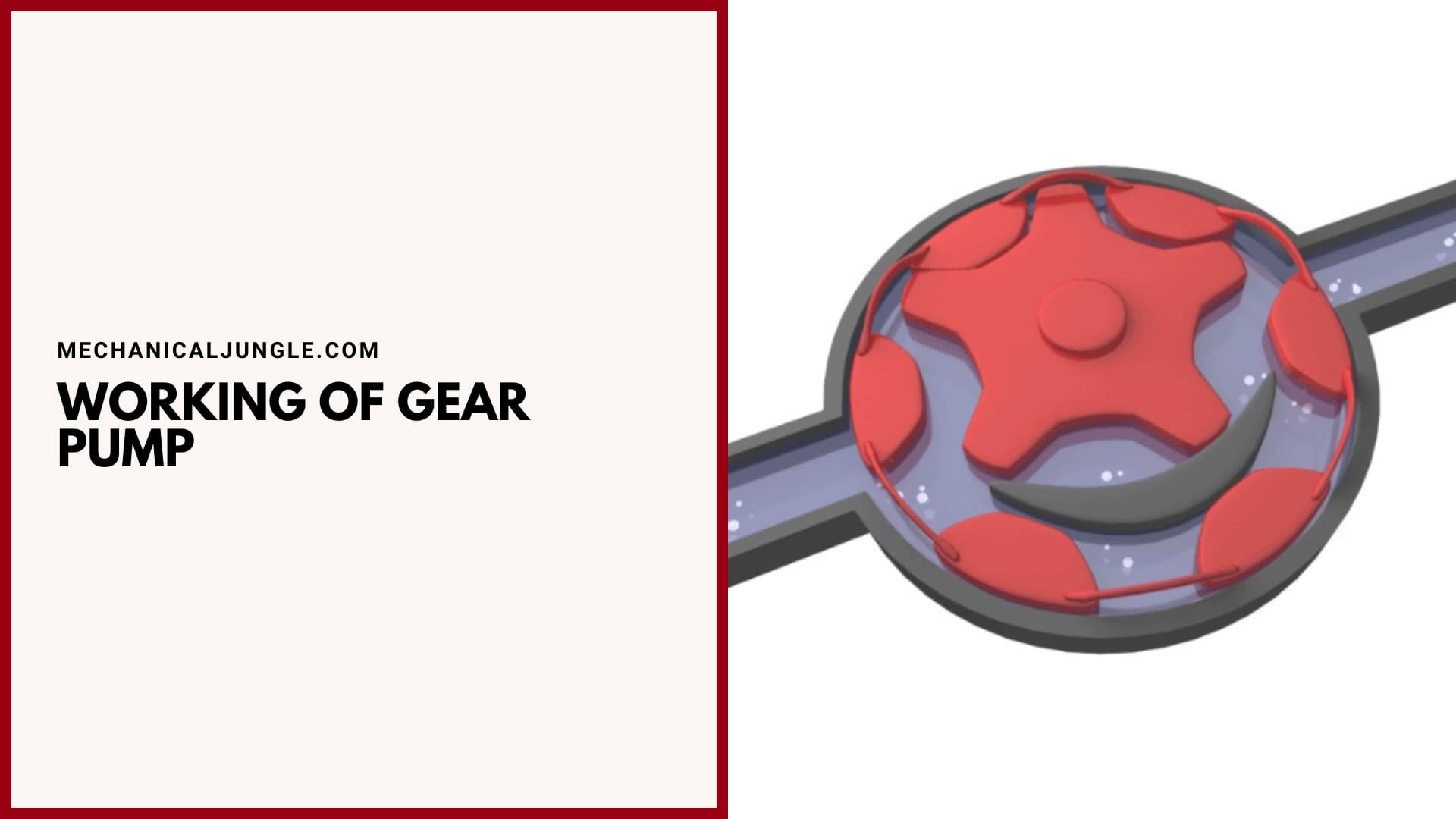
On starting the gear pump, the driving shaft is started by providing power and begins to rotate the driving gear using power from the prime mover. The driver also rotates the forged gear along with the gear as the driver rotates the gear but in the opposite direction. As both gears start rotating, a partial vacuum is created on the suction side.
As soon as the vacuum is created, the liquid in the suction side is sucked towards the gear. After that, sucked liquid gets trapped between the gears & the casing.
Then the liquid trapped between the casing and gear teeth travels along with the rotation of the gear teeth and moves from the suction side to the discharge.
Similarly, the discharge gear from the suction side to the discharge side also has a liquid flow, and the high-pressure liquid discharges the pump from the discharge side.
The fluid from the suction side cannot directly go to the discharge and also from the suction side to the discharge as the two gears are fully engaged, and there is no lag for the fluid to flow.
Also, Read: Parts and Functions of Grinding Machine | Grinding Machine | Grinding Machine Types
Advantages of Gear Pump:
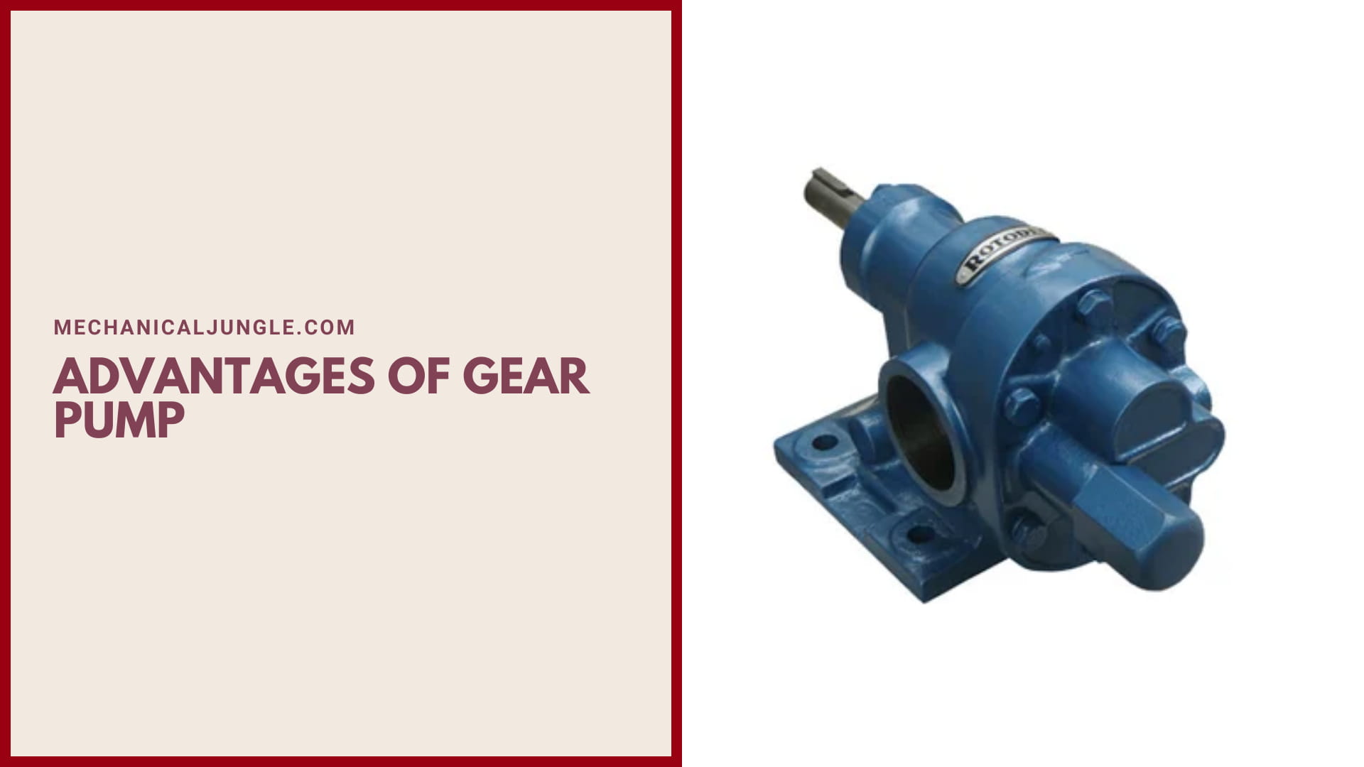
Here, the different Advantages of gear pump are as follows:
- These pumps are very simple & compact, with a very small number of moving parts.
- The maintenance costs of this type of pump are very lows.
- It costs less.
- Gear pumps can be used to generate very high pressures up to 3000 psi.
- It can be used to pumps highly viscous liquids like oil that cannot be pumped using centrifugal pumps.
- There is a very low probability of leakage when pumping a high viscous liquid like oil into the gear pump. Therefore, the efficiency of this pump increases when pumping highly viscous fluids.
- Gear pumps can run in both directions. Therefore, a single pump can be used for both loading and unloading purposes.
- This pump is much less susceptible to contamination.
Also, Read: Watt Governor | Construction of Watt Governor | Working of Watt Governor | Limitations of Watt Governor
Disadvantages of Gear Pump:
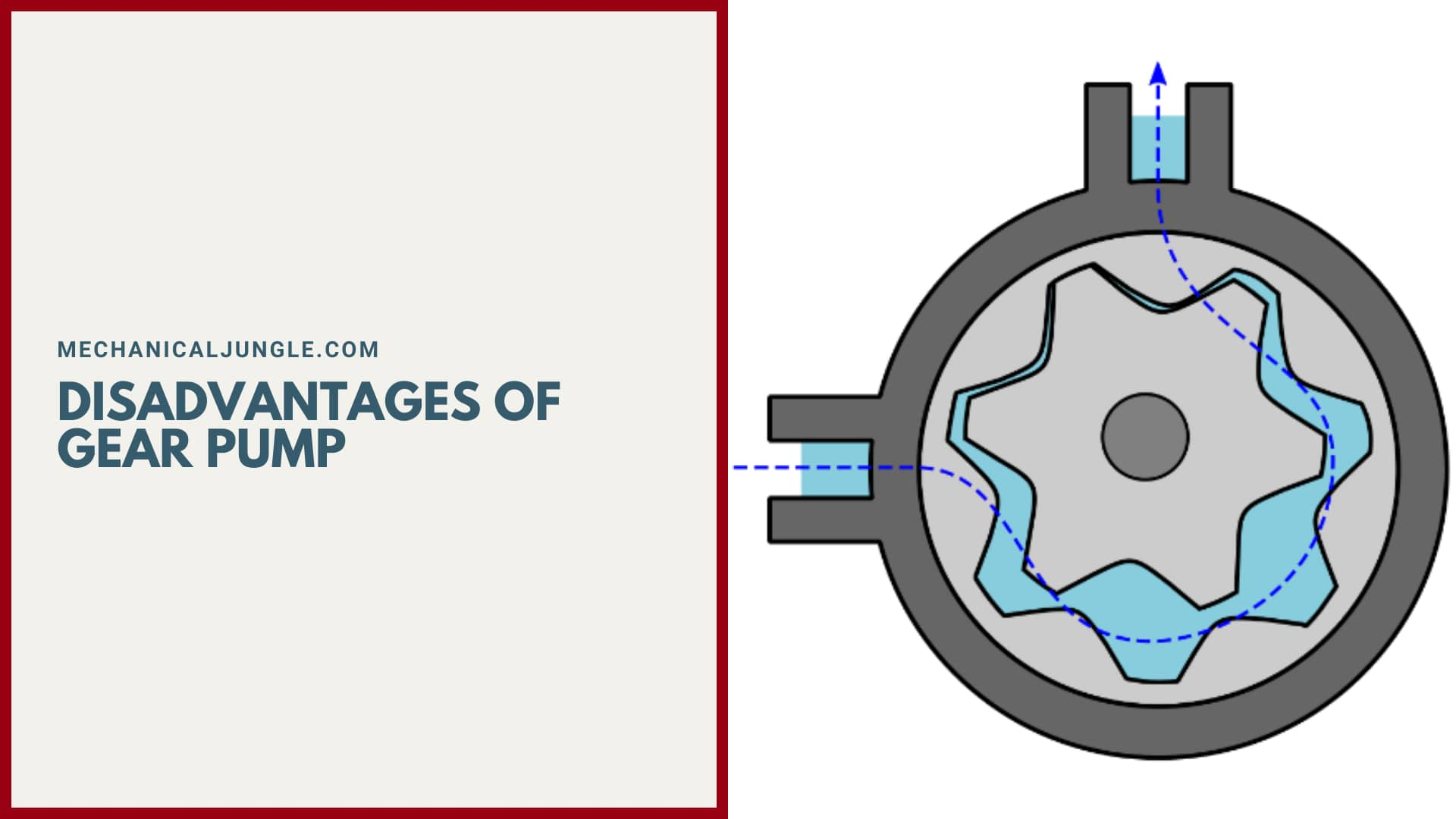
Here, the different Disadvantages of gear pump are as follows:
- Meshing gears are used, friction fluid cannot be used in gear pumps.
- These pumps make a lot of noise.
- The size of gears pumps is limited, so they cannot be used for large bulk flow rates.
Applications of Gear Pump:
Here, the different Applications of gear pumps are as follows:
- These are used in applications where precise dosing is necessary.
- Since the gear pump is not overly affected by the output pressure, it can also be applied in applications where there is an unbalanced supply.
Frequently Asked Questions (FAQ)
Types of Gear Pumps
Generally, gear pumps are of five types
- External Gear Pump
- Internal Gear Pump
- Lobe Pump
- Ge- Rotor (generated rotor) pump
- Screw Pump
Gear Type Positive Displacement Pump
A gear pump is a type of positive displacement (PD) pump. It moves a fluid by repeatedly enclosing a fixed volume using interlocking cogs or gears, transferring it mechanically using a cyclic pumping action. It delivers a smooth pulse-free flow proportional to the rotational speed of its gears.
Helical Gear Pump
A Helical Gear Pump is a type of External Gear Pump used for the transfer of viscous fluids at low speed. Two sets of interlocking gears are offset within the pump head, with 2 gears located at the front of the pump head, and 2 at the rear to ensure the rotary forces remain balanced.
Miniature Gear Pump
These miniature gear pumps feature a compact plastic head and drive. Choose from three model options— nonenclosed OEM, lab, and fully enclosed lab versions.
High-Performance Gear Pump Manufacturers in USA
When it comes to high-performance gear pump manufacturers in the USA, several companies are known for their quality products and expertise. Here are a few notable manufacturers:
- Viking Pump, Inc.: Viking Pump, a subsidiary of IDEX Corporation, is a leading manufacturer of positive displacement pumps, including gear pumps. They offer a wide range of gear pump models designed for various industries, including oil and gas, chemical processing, and food and beverage. Viking Pump is known for its reliability, durability, and innovation in pump technology.
- Moyno, Inc.: Moyno, a division of NOV, specializes in the design and manufacture of progressive cavity pumps, but they also offer gear pumps. Their gear pumps are engineered for precise fluid handling in demanding applications, such as oil and gas, chemical processing, and wastewater treatment. Moyno is recognized for its advanced pumping solutions and high-performance products.
- Roper Pump Company: Roper Pump Company, a subsidiary of Gardner Denver, is a well-established manufacturer of gear pumps with a history dating back to 1857. They provide a wide range of gear pumps suitable for applications in industries like oil and gas, petrochemical, and industrial processing. Roper Pump is known for its robust construction, reliability, and efficient fluid handling capabilities.
- Zenith Pumps: Zenith Pumps, a Colfax Corporation company, specializes in precision gear metering pumps. They manufacture a range of gear pumps designed for applications in the polymer, chemical, and industrial markets. Zenith Pumps’ gear pumps are recognized for their precision, accuracy, and consistent performance.
- Haight Pump: Haight Pump, based in California, has been manufacturing gear pumps since 1950. They offer a diverse range of gear pumps suitable for various applications, including industrial, agricultural, and chemical. Haight Pump is known for its high-quality craftsmanship, durability, and efficient pumping solutions.
Benefits of Using Gear Pumps in Industrial Applications
Gear pumps are commonly used for pumping high viscosity fluids such as oil, paints, resins or foodstuffs. They are also preferred in applications where accurate dosing or high pressure output is required.
Gear Pump Troubleshooting and Maintenance Tips
Troubleshooting Tips:
- Inspect for Leakage: Check for any visible signs of leakage around the pump, including at the seals, connections, and pump housing. Address any leaks promptly, as they can affect pump efficiency and lead to further damage.
- Monitor Pump Noise: Unusual or excessive noise from the pump may indicate a problem. Grinding, squealing, or knocking sounds could be a sign of misalignment, worn bearings, or damaged gears. Investigate the source of the noise and take appropriate action.
- Check Pump Performance: Monitor the pump’s flow rate and pressure. If you notice a significant drop in performance, it may be due to wear, clogging, or an issue with the impeller or gear teeth. Investigate and resolve the cause of reduced performance to ensure proper fluid transfer.
Maintenance Tips:
- Regular Lubrication: Proper lubrication is crucial for gear pump performance and longevity. Follow the manufacturer’s recommendations for lubrication intervals and use the appropriate lubricants to ensure smooth operation and minimize wear.
- Inspect and Clean: Regularly inspect the pump for any debris, sediment, or foreign particles that may accumulate and hinder performance. Clean the pump and its components thoroughly to prevent clogging and potential damage.
- Check Alignment: Ensure that the pump and its associated components, such as the motor and coupling, are properly aligned. Misalignment can cause excessive vibration, increased wear, and reduced pump efficiency. Correct any alignment issues promptly.
Gear Pump Vs. Vane Pump: Which Is More Efficient?
Both gear pumps and vane pumps have their advantages and considerations when it comes to efficiency. Let’s compare the two:
Gear Pump Efficiency:
- Gear pumps are known for their high volumetric efficiency. Their design allows for close tolerances between the gears and the pump housing, resulting in minimal internal leakage and high volumetric efficiency.
- The efficiency of gear pumps can vary depending on factors such as the design, clearances, and operating conditions. Proper maintenance and ensuring tight tolerances are crucial for optimal efficiency.
- Gear pumps are generally more efficient at higher speeds and under continuous operation. They are commonly used in applications where a constant flow rate is required.
Vane Pump Efficiency:
- Vane pumps are also known for their good efficiency, especially at higher speeds. They typically have higher efficiencies compared to gear pumps when operating at high speeds.
- Vane pumps can maintain their efficiency over a broader range of operating speeds compared to gear pumps.
- However, vane pumps may have slightly lower volumetric efficiency compared to gear pumps due to greater internal leakage, especially at low speeds or when the vanes and the pump housing wear over time.
Durable Gear Pump for Hydraulic Systems
When it comes to selecting a durable gear pump for hydraulic systems, several factors should be considered, including the pump’s construction, materials, performance specifications, and reliability. Here are a few key points to keep in mind:
- Construction and Materials: Look for gear pumps specifically designed for hydraulic applications. Opt for pumps with robust construction, such as heavy-duty cast iron or stainless steel housings, to withstand high pressures and provide durability. The gear sets should be made from hardened materials, such as steel or bronze, to resist wear and maintain performance over time.
- Pressure and Flow Requirements: Consider the pressure and flow requirements of your hydraulic system. Choose a gear pump that can meet or exceed these specifications. Look for pumps that offer a wide operating range to accommodate varying system demands.
- Efficiency and Performance: Evaluate the pump’s efficiency to minimize energy consumption and reduce operating costs. Look for pumps with high volumetric efficiency, low internal leakage, and precise gear tolerances. Consider pumps with advanced design features like pressure-balanced bushings or internal helical gears, which can enhance performance and reduce wear.
Gear Pump Types
There are two types of gear pumps – external gear pumps and internal gear pumps. External gear pumps make use of two external opposing gears (typically spur gears) in transferring the fluid type. Internal gear pumps use one outer ring gear and one internal pinion gear running inside the ring gear.
Gear Pump Parts and Function
An external gear pump consists of a suction port, discharge port, gears, bearings, and a casing. Gears in an external gear pump are installed parallel to each other. A shaft is installed through the centre axis of each gear and bearings hold each shaft in position.
Gear Pump Working Principle
How does a gear pump work? Gear pumps use the actions of rotating cogs or gears to transfer fluids. The rotating element develops a liquid seal with the pump casing and creates suction at the pump inlet. Fluid, drawn into the pump, is enclosed within the cavities of its rotating gears and transferred to the discharge.
Gear Pump Applications
- Water.
- Various fuel oils and lube oils (engine and gear box lubrication systems)
- Chemical additive and polymer metering.
- Chemical mixing and blending.
- Industrial, agricultural and mobile hydraulic applications (tractors, log splitters, lifts, etc.)
Gear Pump Function
A gear pump moves a fluid by repeatedly enclosing a fixed volume within interlocking cogs or gears, transferring it mechanically to deliver a smooth pulse-free flow proportional to the rotational speed of its gears.
What Is a Gear Pump Used For?
Gear pumps are commonly used for pumping high viscosity fluids such as oil, paints, resins or foodstuffs. They are preferred in any application where accurate dosing or high pressure output is required.
How Does a Gear Pump Operate?
Gear pumps work by trapping fluid between the teeth of two or three rotating gears. Often, they are magnetically driven, which means they use less “wetted” materials for greater chemical compatibility. Gear pumps move a cavity that rotates rather than reciprocates.
Like this post? Share it with your friends!
Suggested Read –
- Centrifugal Pump Working Principle
- Chip Thickness Ratio | Shear Angle of Chip Thickness Ratio
- Resistance Projection Welding | Working of Resistance Projection Welding
- Parts of Turret Lathe | Working of Turret Lathe | Types of Turret Lathe | Advantages of Turret Lathe
- Techniques of Gas Welding | Parts of Welding Torch | Working of Gas Welding | Types of Gas Welding | Types of Flames in Gas Welding
- Parts of Reciprocating Pump | Definition of Reciprocating Pump | Working of Reciprocating Pump | Mathematical Analysis of Reciprocating Pump